
Monitoring device and monitoring method based on visual image

A monitoring device and visual image technology, applied in the direction of image communication, color TV parts, TV system parts, etc., can solve the problems of single working mode, single function, small monitoring range, etc., and achieve the effect of wide application range

Inactive Publication Date: 2012-09-26
徐贵力
View PDF6 Cites 36 Cited by
  • Summary
  • Abstract
  • Description
  • Claims
  • Application Information

AI Technical Summary

Problems solved by technology

However, the working mode of the existing monitoring devices is relatively single. One set of monitoring devices cannot meet the above-mentioned multiple requirements at the same time, and cannot realize the above-mentioned multiple functions at the same time. Often, two sets of different monitoring devices are required to perform their respective functions.
Therefore, existing monitoring devices generally have shortcomings such as small monitoring range, single function, and poor pertinence.

Method used


Image

  • Monitoring device and monitoring method based on visual image
  • Monitoring device and monitoring method based on visual image
  • Monitoring device and monitoring method based on visual image

Examples


Embodiment Construction

[0043] The present invention will be specifically introduced below in conjunction with the accompanying drawings and specific embodiments.

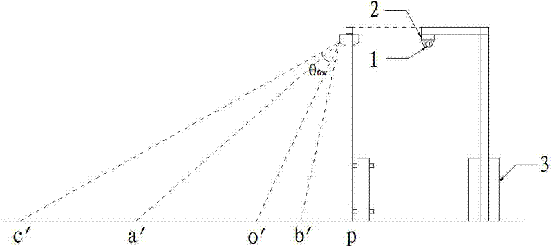
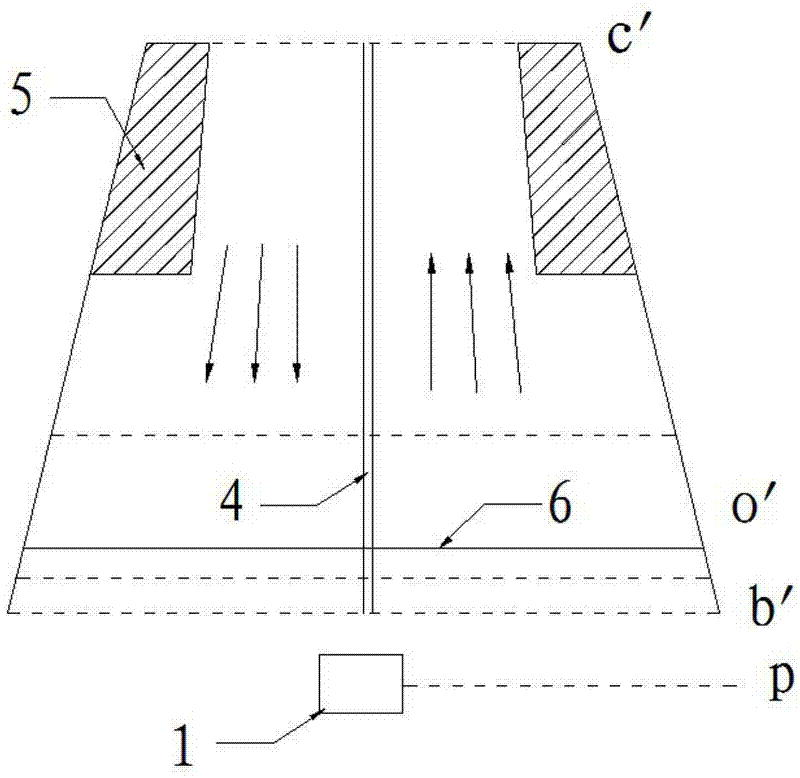
[0044] refer to figure 1 , a visual image-based monitoring device of the present invention includes: a camera 1, an electric pan-tilt 2 and a monitoring processor 3, which form a wired communication connection or a wireless communication connection capable of transmitting data information.

[0045] The camera 1 is used to collect images, controlled by a program and able to focus to obtain clear images, and the images are transmitted to the monitoring processor 3 by wired or wireless communication.

[0046] As a preferred solution, the camera 1 is a camera with a motorized three-variable lens.

[0047]As a preferred solution, in order to be able to capture and record high-definition images, the camera 1 is a high-definition high-speed camera with a resolution of 1920×1080 or more, and can be used as a high-definition high-speed camera wit...


PUM


Abstract

The invention provides a monitoring device and a monitoring method based on a visual image. The device comprises a focusing camera, an electric rotational station for controlling omni-directional rotation of the camera, and a monitoring processor for controlling the camera and the electric rotational station and receiving and processing data information fed back by the camera and the electric rotational station. The monitoring processor comprises a human-computer interaction module, a camera control module, a target detection module, an image calibration module and a video conversion module. The method for applying the device to monitor a specific target can be applied in two working modes: ifa target image in a panoramic monitoring video is not distinct,a monitoring system employs real-time monitoring, detection, tracking and automatic focusing to capturea high definition image of the target; and if a target image in the panoramic monitoring video is distinct, video recording and then analyzing are employed for monitoring, and video can be played backwards. Different working modes are employed according to different situations to guarantee that image and the video containingthe distinct features of the specific image target can be finally obtained.

Description

technical field [0001] The invention belongs to the field of security and intelligent transportation, and in particular relates to a monitoring device and a monitoring method based on visual images. Background technique [0002] With the rapid development of our society, security and traffic problems are becoming more and more obvious, which has a great impact on people's travel and even life safety. [0003] The monitoring device based on visual images has been widely used due to its unique advantages. For example, it is installed on the road to monitor whether there are vehicles crossing or pressing double yellow lines for illegal driving, whether there are vehicles riding on the stop line, etc. Or monitor whether there are vehicles parked in the no-parking area. For some application scenarios, such as highway toll stations, it is necessary to monitor whether there are vehicles driving illegally over and over the double yellow lines in the middle of the road, and to monit...

Claims


Application Information

Patent Timeline
IPC IPC(8): G08G1/01H04N5/232H04N7/18
Inventor 徐贵力杨小伟李旭吕温
Owner 徐贵力
Learn More