Power electronic circuit

A power electronic circuit and capacitor technology, which is applied to electrical components, output power conversion devices, and AC power input to DC power output, etc. Avoid the effect of long charging and discharging paths

Active Publication Date: 2012-09-26
HUAWEI DIGITAL POWER TECH CO LTD
View PDF5 Cites 14 Cited by
  • Summary
  • Abstract
  • Description
  • Claims
  • Application Information

AI Technical Summary

Problems solved by technology

[0006] Since one of the charging paths involves three series-connected switching tubes, the loop path is long, and the reverse recovery characteristics of the anti-parallel diode of the first switching tube Q1 have a great influence on the voltage spike of the third switching tube Q3

Method used


Image

  • Power electronic circuit
  • Power electronic circuit
  • Power electronic circuit

Examples


Embodiment Construction

[0028] In order to make the above objects, features and advantages of the present invention more comprehensible, the present invention will be further described in detail below in conjunction with the accompanying drawings and specific embodiments.

[0029] In view of this, the object of the present invention is to provide a power electronic circuit for avoiding the problem of a long charging and discharging path of the junction capacitance of the switching tube.

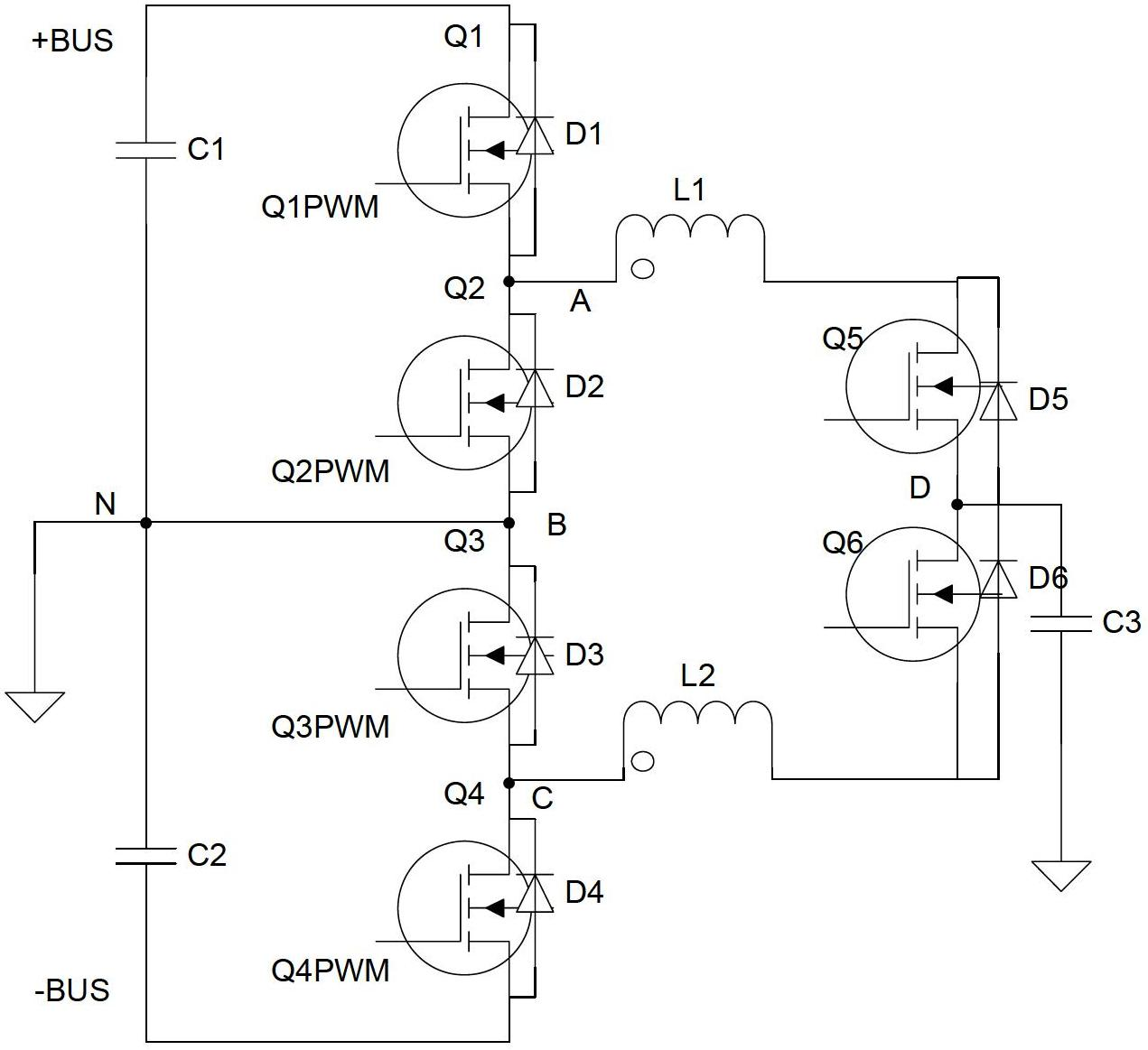
[0030] see figure 1 , which is a structural diagram of the power electronic circuit of the first embodiment of the present invention.

[0031] The power electronic circuit according to the first embodiment of the present invention includes: a first switching tube Q1, a second switching tube Q2, a third switching tube Q3, a fourth switching tube Q4, a fifth switching tube Q5, and a sixth switching tube Q6, And the first inductance L1 and the second inductance L2.

[0032] The first switching tube Q1 is connected to...


PUM


Abstract

The invention discloses a power electronic circuit. The power electronic circuit comprises a first switching tube, a second switching tube, a third switching tube, a fourth switching tube, a fifth switching tube, a sixth switching tube, a first capacitor, a second capacitor, a first inductor and a second inductor, wherein the first capacitor and a second capacitor are connected in series between an input positive generatrix and an input negative generatrix; the first capacitor and the second capacitor are connected with a fifth node; the first switching tube, the second switching tube, the third switching tube and the fourth switching tube are connected in series between the first capacitor and the second capacitor in sequence; the first switching tube and the second switching tube are connected with the first node; the second switching tube and the third switching tube are connected with a second node; the third switching tube and the fourth switching tube are connected with a third node; the fifth switching tube and the sixth switching tube are connected with a fourth node; the switching tube is connected with the first node through the first inductor; the sixth switching is connected with the third node through a second inductor; and the second node is connected with the fifth node. By adopting the embodiment of the invention, the problem of long switching tube junction capacitance charging and discharging path is avoided.

Description

technical field [0001] The invention relates to the technical field of power electronic systems, in particular to a power electronic circuit. Background technique [0002] Existing power electronic circuits, such as three-level inverters, include four switching tubes—first, second, third, and fourth switching tubes Q1, Q2, Q3, and Q4—connected in series at the positive and negative ends of the DC bus in sequence. Each switch tube has a driving control signal. [0003] During the positive half cycle of the inverter output voltage, the second switching tube Q2 is controlled to be normally on, the fourth switching tube Q4 is normally closed, and the first switching tube Q1 and the third switching tube Q3 are turned on in accordance with SPWM complementarity and their dead zone is guaranteed. [0004] During the negative half cycle of the output voltage, the third switching tube Q3 is controlled to be normally on, the first switching tube Q1 is normally off, and the fourth swit...

Claims


Application Information

Patent Timeline
IPC IPC(8): H02M7/483
CPCH02M7/487H02M2001/0064H02M1/0064
Inventor 章陶刘克雷李俊林
Owner HUAWEI DIGITAL POWER TECH CO LTD
Why Eureka
Try Eureka