

Hardening accelerator for hydraulic composition
A composition and hydraulic technology, which is applied in the field of early strength agents for hydraulic compositions, can solve the problems of reducing energy costs, rising energy costs, and reducing the curing temperature
Active Publication Date: 2012-09-26
KAO CORP
View PDF11 Cites 6 Cited by
- Summary
- Abstract
- Description
- Claims
- Application Information
AI Technical Summary
Problems solved by technology
[0003] In addition, the shortening of the curing time of steam curing is usually sought, but the energy cost of steam curing is increased due to the use of steam. From the viewpoint of reducing energy cost, that is, shortening the steam curing time and lowering the curing temperature, it is also eagerly expected to use steam curing. method
Method used
View moreImage
Smart ImageViewing Examples


Examples
Embodiment
[0098] The following test examples describe the implementation or comparison of the present invention. The test examples describe examples or comparisons of the present invention and are not intended to limit the present invention.
Login to View More PUM
| Property | Measurement | Unit |
|---|---|---|
| strength | aaaaa | aaaaa |
| density | aaaaa | aaaaa |
Abstract
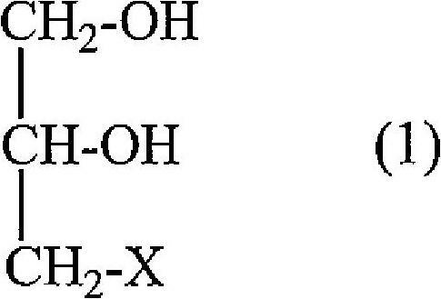
Provided is a hardening accelerator for a hydraulic composition, which comprises a specific compound (1) such as glycerin and one or more inorganic salts (A ) selected from alkali metal sulfates and alkali metal thiosulfates, wherein the molar ratio of the compound (1) and the inorganic salt (A) is 5 / 95 to 45 / 55 by compound (1) / inorganic salt (A).
Description
technical field [0001] The present invention relates to an early strengthening agent for a hydraulic composition, an additive composition for a hydraulic composition, a hydraulic composition, a method for producing the hydraulic composition, and a method for producing a hardened body of the hydraulic composition. Background technique [0002] Concrete products are made by mixing materials such as cement, aggregate, water and dispersants and pouring them into various types of boxes, and then undergoing a curing (hardening) process to make products. From the point of view of improving productivity, that is, increasing the turnover rate of the mold box, it is important to exhibit high strength at the initial material age. For this reason, the following countermeasures are proposed: (1) Use early-strength cement as cement; (2) Use various polymers Carboxylic acid compounds are used as admixtures to reduce the amount of water in cement compositions; (3) Steam curing is used as a ...
Claims
Login to View More Application Information
Patent Timeline
 Patent Type & AuthorityApplications(China)
IPC IPC(8): C04B22/14C04B24/02C04B24/22C04B24/26C04B28/02C04B103/14
CPCC04B28/02C04B2103/24C04B40/0039C04B2103/14C04B22/14C04B24/122C04B24/226C04B22/147C04B24/02C04B14/06C04B2103/408
Inventor滨井利正吉川洋平光田义德福岛哲朗下田政朗名嘉良仁吉浪雄亮川上博行
OwnerKAO CORP