Pulverized coal carriability improver

a carriability improver and pulverized coal technology, applied in the field of pulverized coal carriability improvers, can solve the problems of difficult to continue the restricted kind of coal usable for pulverized coal injection, and difficult to maintain stable injection of pulverized coal

Inactive Publication Date: 2000-07-04
KAO CORP
View PDF15 Cites 72 Cited by
  • Summary
  • Abstract
  • Description
  • Claims
  • Application Information

AI Technical Summary

Problems solved by technology

However, such furnaces as well as blast furnaces have problems resulting from the use of pulverized coal.
Pulverized coal injection is conducted through the steps of preparation of pulverized coal from raw coal by dry pulverization, classification of the obtained pulverized coal, storage of the resulting pulverized coal in a hopper and discharge thereof from the hopper, pneumatic transportation thereof through piping, injection thereof into a metallurgical or combustion furnace through an injection port, and combustion thereof in the furnace, among which the discharge of pulverized coal from a hopper and the pneumatic transportation thereof through piping are accompanied with the problems which will now be described.
Accordingly, it is difficult to continue t...

Method used


Image

  • Pulverized coal carriability improver
  • Pulverized coal carriability improver
  • Pulverized coal carriability improver

Examples


example 324

An example of the application to pulverized coal injection equipment for blast furnace will now be described.

Conditions:

injection rate of pulverized coal: 40 t / hr

transportability improver: ammonium sulfate

amount: 0 or 0.3 wt. %

pulverized coal: content of particles 106 .mu.m or below in diameter: 95%

water content: 1.5%

av. HGI of raw coal: 45, 55, 70

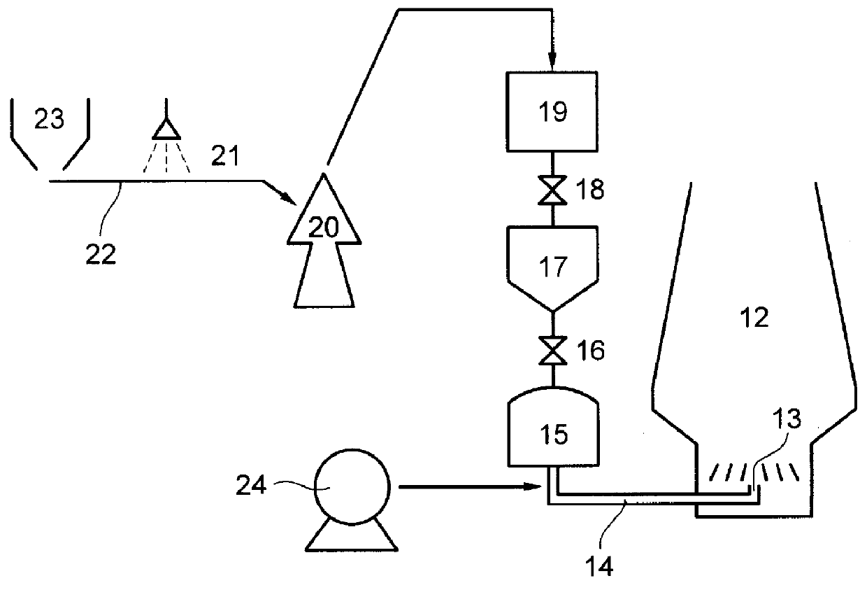
A schematic view of the pulverized coal injection equipment for blast furnace used in this Example is shown in FIG. 3, wherein numeral 12 refers to a blast furnace, 13 refers to an injection port, 14 refers to injection piping, 15 refers to a distribution tank, 16 refers to a valve, 17 refers to an equalization tank, 18 refers to a valve, 19 refers to a storage tank for pulverized coal, 20 refers to a coal pulverizer, 21 refers to a nozzle for spraying additives, 22 refers to a belt conveyor for transferring coal, 23 refers to a hopper for receiving coal, and 24 refers to an air or nitrogen compressor.

Coal was thrown into the hopper 23 and...

example 325

An example of the application to a pulverized coal firing boiler will now be described.

transportability improver: ammonium sulfate

amount: 0 or 0.3 wt. %

pulverized coal: content of particles 106 .mu.m or below in diameter: 95%

water content: 1.5%

av. HGI of raw coal: 45, 55, 65, 75

A schematic view of the pulverized coal firing boiler used in this Example is shown in FIG. 7, wherein numeral 25 refers to a combustion chamber, 26 refers to a burner, 27 refers to injection piping, 28 refers to a storage tank for pulverized coal, 29 refers to a coal pulverizer, 30 refers to a nozzle for spraying additives, 31 refers to a conveyor for transferring coal, 32 refers to a hopper for receiving coal, and 33 refers to an air or nitrogen compressor.

Coal was thrown into the hopper 33 and fed into the pulverizer 29 by the conveyor 31, while a transportability improver was sprayed on the coal through the nozzle 30 in the course of this step. The coal was pulverized into particles having the above diame...


PUM

PropertyMeasurementUnit
Percent by massaaaaaaaaaa

Abstract

PCT No. PCT/JP97/00668 Sec. 371 Date Sep. 25, 1998 Sec. 102(e) Date Sep. 25, 1998 PCT Filed Mar. 5, 1997 PCT Pub. No. WO97/36009 PCT Pub. Date Oct. 2, 1997The use of pulverized coal as the fuel to be injected into metallurgical or combustion furnace becomes possible enabled by improving the transportability thereof. Further, a pulverized coal is provided, which is inhibiting from bridging or channeling in a hopper, or piping choking. A water-soluble inorganic salt having a polar group is made to adhere to pulverized coal which is prepared from raw coal having an average HGI of 30 or above and which is in a dry state at the injection port of a metallurgical or combustion furnace, The inorganic salt is selected from among BaCl2, CaCl2, Ca(NO2)2, Ca(NO3)2, Ca(ClO)2, K2CO3, KCl, MgCl2, MgSO4, NH4BF4, NH4Cl, (NH4)2SO4, Na2CO3, NaCl, NaClO3, NaNO2, NaNO3, NaOH, Na2S2O3, Na2S2O5, HNO3, H2SO4, H2CO3, and HCl.

Description

This application is the national phase under 35 U.S.C. .sctn.371 of prior PCT International Application No. PCT / JP97 / 00668 which has an International filing date of Mar. 5, 1997 which designated the United States of America, the entire contents of which are hereby incorporated by reference.1. Industrial Field of ApplicationThe present invention relates to a transportability improver for pulverized coal which can improve the transportability of pulverized coal to enable the stable injection of pulverized coal into a metallurgical or combustion furnace at an enhanced feed rate, and a process for operating a metallurgical or combustion furnace by the use of the improver.2. Prior ArtIn the operation of a metallurgical furnace such as a blast furnace, it has been a general practice to charge coke and iron ore into the furnace from the top alternately. However, another operation process has recently been employed frequently, wherein pulverized coal which is inexpensive and excellent in co...

Claims


Application Information

Patent Timeline
IPC IPC(8): C21B5/00F23K1/00F23K3/00F23K3/02C10L5/00F23C99/00
CPCC21B5/003F23K1/00F23K3/00F23K3/02F23K2201/505C21B5/00
Inventor ONO, REIJINAKAYA, TAKASHIKIMURA, YOSHIOKAMIJO, TSUNAOMIYAMOTO, KENICHIMATOBA, TAKASHIOHASHI, HIDEMIICHIMOTO, TAKEHIKO
Owner KAO CORP
Why Eureka
Try Eureka