
Optical filter comprising solar blind dyes and UV-transparent substrates

a technology of optical filter and blind dye, applied in the field of selective optical filter, can solve the problems of inability to use these emission lines to image corona, weak relative strength of emission lines, and ultraviolet light,

Inactive Publication Date: 2005-04-21
THE UNITED STATES OF AMERICA AS REPRESENTED BY THE SECRETARY OF THE NAVY
View PDF10 Cites 70 Cited by
  • Summary
  • Abstract
  • Description
  • Claims
  • Application Information

AI Technical Summary

Benefits of technology

The present invention provides an optical filter that can absorb UV radiation and transmit UV radiation with high efficiency. The filter comprises an organic, solar blind filter dye and a UV-transparent, non-scattering and chemically stable substrate. The filter can be made using a nanoporous silica glass solid that is substantially UV-transparent and a UV-transparent solvent that matches the refractive index of the glass solid. The filter can be used to make a wide variety of optical devices.

Problems solved by technology

The detection of ultraviolet (UV) light during daylight conditions is an important problem for both commercial and military applications.
These emission lines are, however, very weak relative to daytime background solar radiation.
It is, therefore, not possible to use these emission lines to image corona during the daytime, even when narrow bandpass filters and applying background subtraction method.
However, due to the extremely high actinic flux of solar radiation, it is still difficult to design a very sensitive optical system that can be used in broad daylight to detect very low levels of UV radiation.
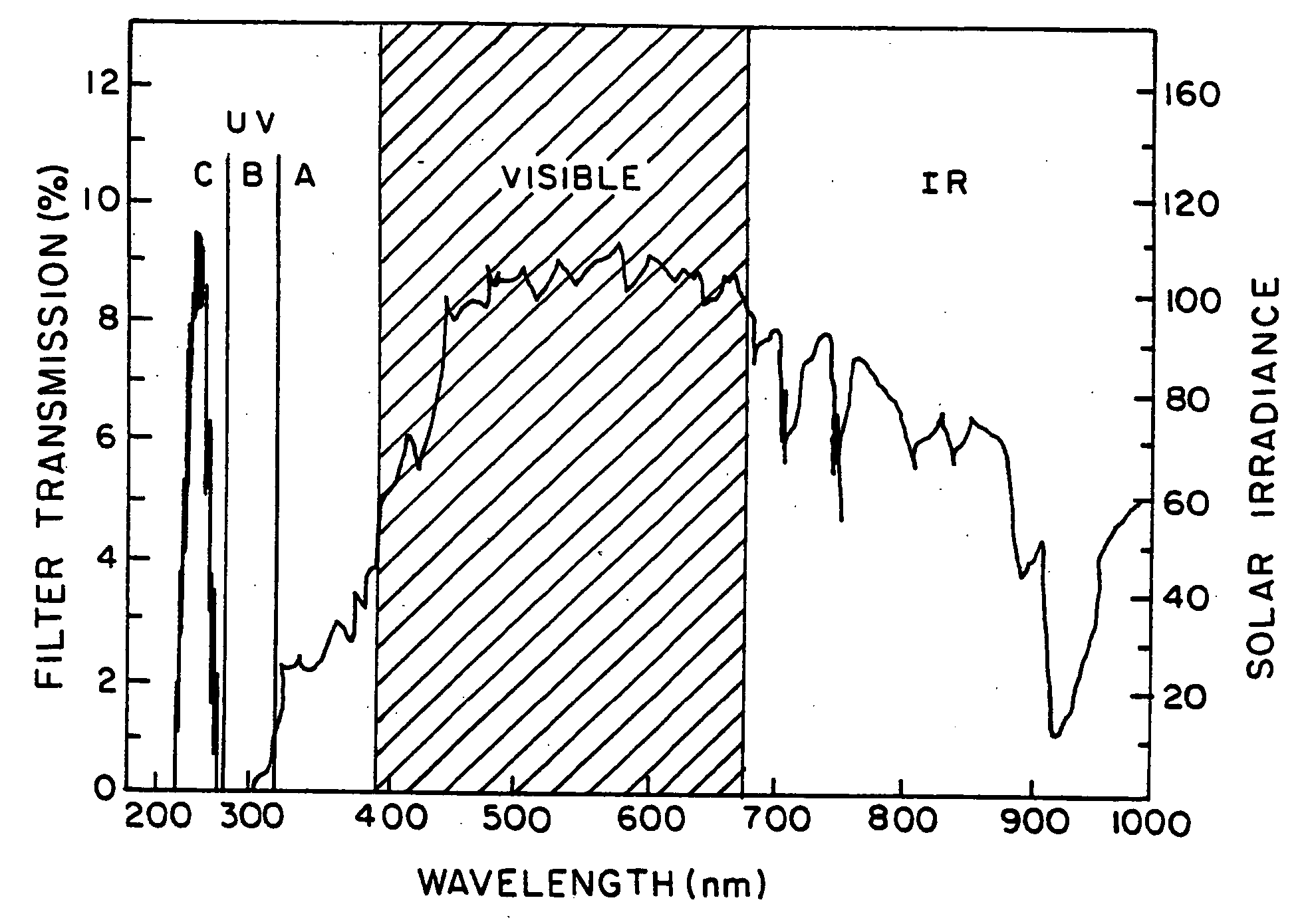
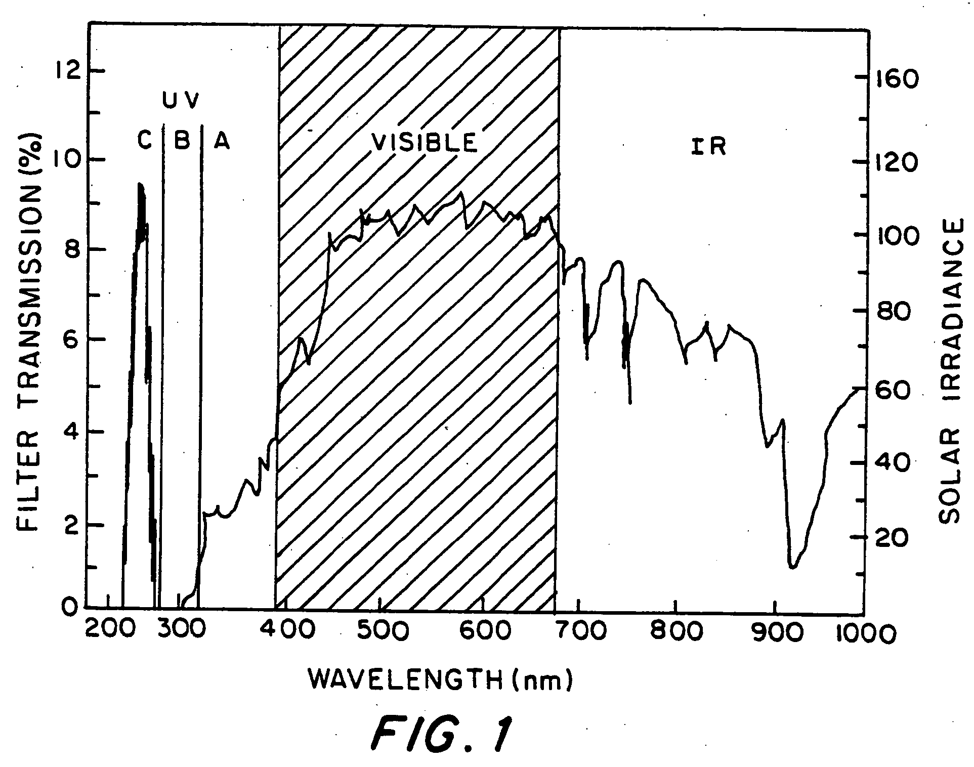
The spectral distribution of radiation from the sun is similar to that of a 6,000 degree black-body radiator, and the detection of an ultraviolet emission source, such as a fire or a rocket plume, during the day is complicated even by the modest amount of UV light emitted by the sun that is not fully absorbed by the earth's atmosphere.
As the wavelength of light becomes shorter in the UV range, prior optical filters suffer from many disadvantages, such as poor optical performance, limited physical longevity, high autofluorescence, poor imaging quality of the transmitted radiation, and transmitted wavelength instability.
However, this material, as well as filters using rare earth ions as crystalline hosts, are very high in cost because of the need to grow single crystals.
Moreover, they typically have poor thermal and moisture stability.
However, the polyvinyl alcohol substrate in which the organic dye is incorporated in these filters is also susceptible to changes in humidity and to environmental degradation.
Still other means include glass substrates, but glass materials often result in broader absorptions than desired, and may tend to fluoresce.
Thus, they are not usually desirable as filter materials for optical reasons.
Further, they require fabrication at high temperatures to solvate materials to be incorporated in the glass.
Specifically, even if UV-transparent glass were used, it would not be possible to dissolve the organic dyes desired into UV transparent glass substrate, because the organic dyes would be unstable at the high processing temperatures required.
However, these substrates would either produce an unacceptable degree of scattering or would exhibit some of the same problems experienced with glass discussed above.
Layered dielectric or rugate filters can also be used as wavelength-selective filters in the UV region of the spectrum, but they have a strong angular dependence to the filtering action and are also expensive to produce.
Therefore, they would not be acceptable for tracking UV-emitting sources over a large area or wide angle of view.

Method used


Image

  • Optical filter comprising solar blind dyes and UV-transparent substrates
  • Optical filter comprising solar blind dyes and UV-transparent substrates
  • Optical filter comprising solar blind dyes and UV-transparent substrates

Examples


example 1

Chlorination of 2,7-Dimethyl1-3,6-diazacyclohepta-1,6-diene Perchlorate

[0069] A flask is charged with 0.0135 moles of the 2,7-dimethyl-3,6-diazacyclohepta-1,6-diene perchlorate and 0.0171 moles of N-chlorosuccinimide in 150 ml carbon tetrachloride, and the resulting mixture was refluxed for about 3 hours at 76° C. The resulting mixture contained several milliliters of a yellowish liquid that was immiscible with the nonpolar carbon tetrachloride solvent, which was clear. The yellowish liquid layer was separated off and diluted with distilled water to about four times its initial volume. This water solution was allowed to stand in an open beaker at room temperature for several hours of slow evaporation. Clear, needle-like crystals then precipitated out, and then were filtered off and washed with fresh carbon tetrachloride. A total of three precipitation / filtering cycles were performed on the mixture, with each cycle yielding about 100 mg of high quality crystalline precipitate.

[0070...

example 2

Preparation Chlorinated Dye in Polyvinyl Alcohol Thin Films

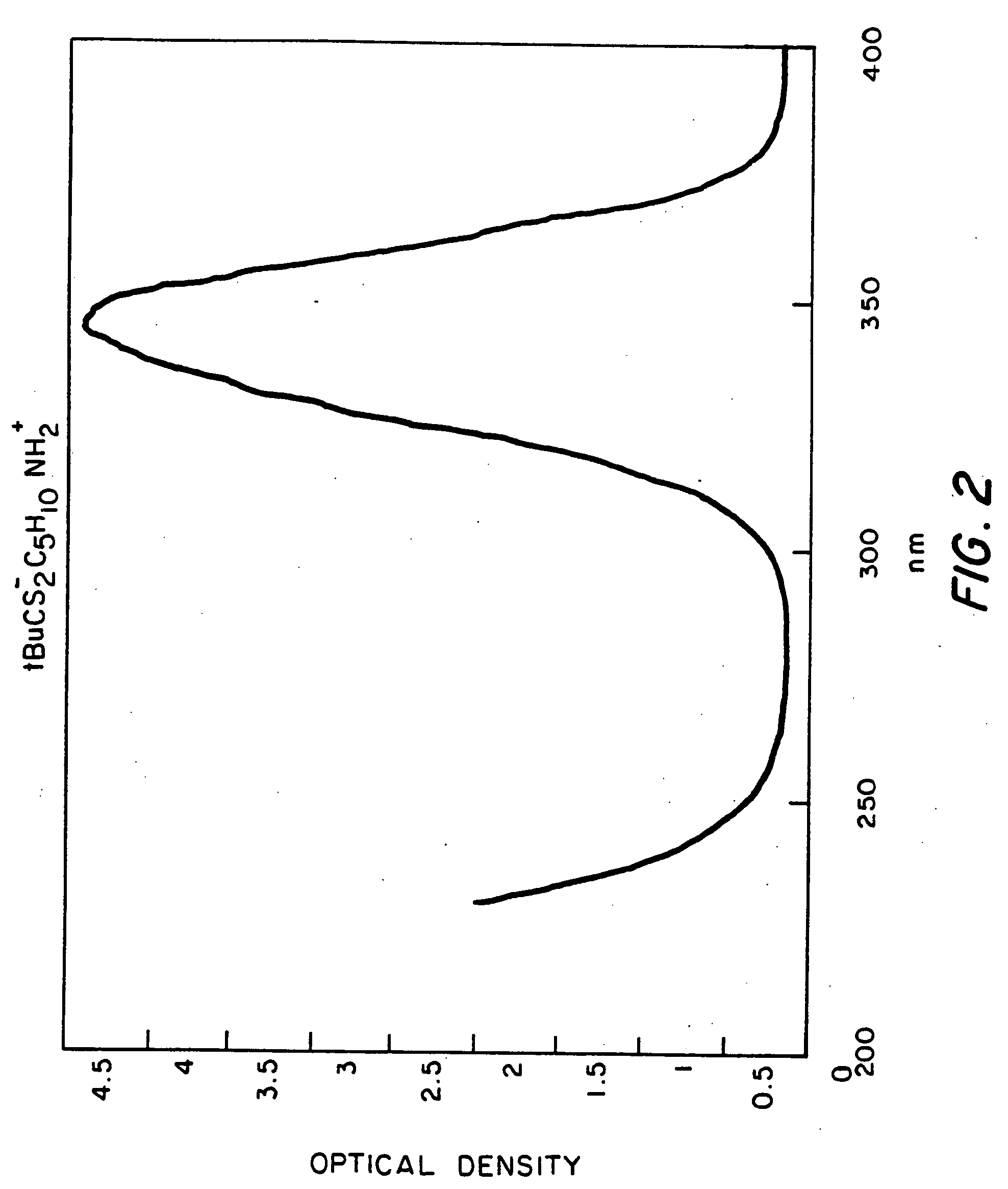
[0073] Thin films of polyvinyl alcohol (PVA) were grown on a quartz substrate from the evaporation of water solutions of PVA that also contained optically dense amounts of the chlorinated produce of Example 1. A sufficient dye concentration was needed to provide an absorbance of about 40 OD at the 346 nm maximum. Using Beer's law, i.e.,

[0074] Absorbance=(chromophore extinction coefficient) (concentration) (pathlength), it was calculated that a 40 OD absorbance would required a (concentration)×(pathlength) product of 0.002 moles-cm / liter. The pathlength was determined experimentally by finding the volume of PVA solution needed to coat the substrate and dividing by the area of the substrate. For the PVA solution, this initial pathlength was on the order of 0.4 nm, and thus the desired initial dye concentration was 0.05 moles / liter. As the water evaporated and the film formed, the (concentration)×(pathlength) produce remained...

example 3

Preparation Chlorinated Dye in Porous Glass Substrate

[0075] The filter using an organic dye in porous glass was prepared by first drying the Vycor disks overnight at 100° C. The disks were then soaked overnight in a 0.1% aqueous solution of the dye. The disks were then heated on a hot plate to remove the water. The disks were then filled with index matching solvent by immersing them in either diethyl succinate, diethyl phthalate or dibutyl phthalate.

[0076]FIG. 7A illustrates the relative Transmission of a filter of the invention comprising the dye prepared in Example 1 incorporated into a porous glass filter with dibutyl phthalate as a solvent. FIG. 7B shows the corresponding absorbance spectrum. Accordingly, the optical performance of the filter of the invention was substantially equal to that of the same dyes in polyvinyl alcohol. However, the dyes of the invention were significantly more stable under adverse conditions and / or long exposures to ambient conditions.


PUM

PropertyMeasurementUnit
wavelengthaaaaaaaaaa
pressureaaaaaaaaaa

Abstract

The invention provides an optical filter comprising: a. an organic, solar blind filter dye; and b. a UV-transparent, non-scattering and chemically stable substrate. The substrate may be a UV-transparent nanoporous silica glass solid having pores that are substantially filled with a UV-transparent solvent, which has been selected to dissolve said dye and also to match the refractive index of the nanoporous silica glass solid. Alternatively, the substrate may be a UV-transparent inorganic salt compressed to form a solid body. The invention also provides for methods of making these embodiments and an optical device comprising such an optical filter. The filter provides an efficient solar blind filter that is chemically and dimensionally stable.

Description

BACKGROUND OF THE INVENTION [0001] 1. Field of the Invention [0002] The present invention relates to selective optical filtration in the ultraviolet region of the spectrum. More particularly, the invention relates to the incorporation of organic dyes, which block unwanted ultraviolet (UV) wavelengths, in substrates that offer good transparency in the UV region of the electromagnetic spectrum to wavelengths as short as 200 nm. [0003] 2. Description of Related Art [0004] Optical filters are passive components whose basic function is to define or improve the performance of optical systems. Applications of optical filters generally can be as diverse as anti-glare computer screens, laser devices such as ophthalmic surgical lasers, sighting devices, etc. Many applications and instruments exist where optical filters are used to tune the optical behavior of light in the ultraviolet range (typically wavelengths shorter than 400 nm). Some applications include water purification, blood chemist...

Claims


Application Information

Patent Timeline
Patent Type & Authority Applications(United States)
IPC IPC(8): G02B5/20
CPCB82Y20/00B82Y30/00Y10S428/913Y10S977/70G02B5/208Y10T428/249969Y10T428/249975Y10T428/249956Y10T428/249953
Inventor PONG, RICHARD G.S.FLOM, STEVEN R.SHIRK, JAMES S.
Owner THE UNITED STATES OF AMERICA AS REPRESENTED BY THE SECRETARY OF THE NAVY
Learn More