Speaker and acoustic equipment including the speaker
What is AI technical title?
AI technical title is built by Patsnap AI team. It summarizes the technical point description of the patent document.
A loudspeaker and magnetic circuit technology, applied in the field of loudspeakers, can solve the problem that the influence of the main frequency band of peak/sag becomes larger and so on
Active Publication Date: 2012-09-26
PANASONIC INTELLECTUAL PROPERTY MANAGEMENT CO LTD
View PDF7 Cites 8 Cited by
Summary
Abstract
Description
Claims
Application Information
AI Technical Summary
This helps you quickly interpret patents by identifying the three key elements:
Problems solved by technology
Method used
Benefits of technology
Problems solved by technology
In short, the influence of the peak / sag caused by the above-mentioned conventional structure on the main frequency band becomes larger
Method used
Image
Click on the blue label to locate the original text in one second.
Reading with bidirectional positioning of images and text.
Examples
Embodiment approach 1
[0050] Hereinafter, speaker 100 in Embodiment 1 will be described using drawings.
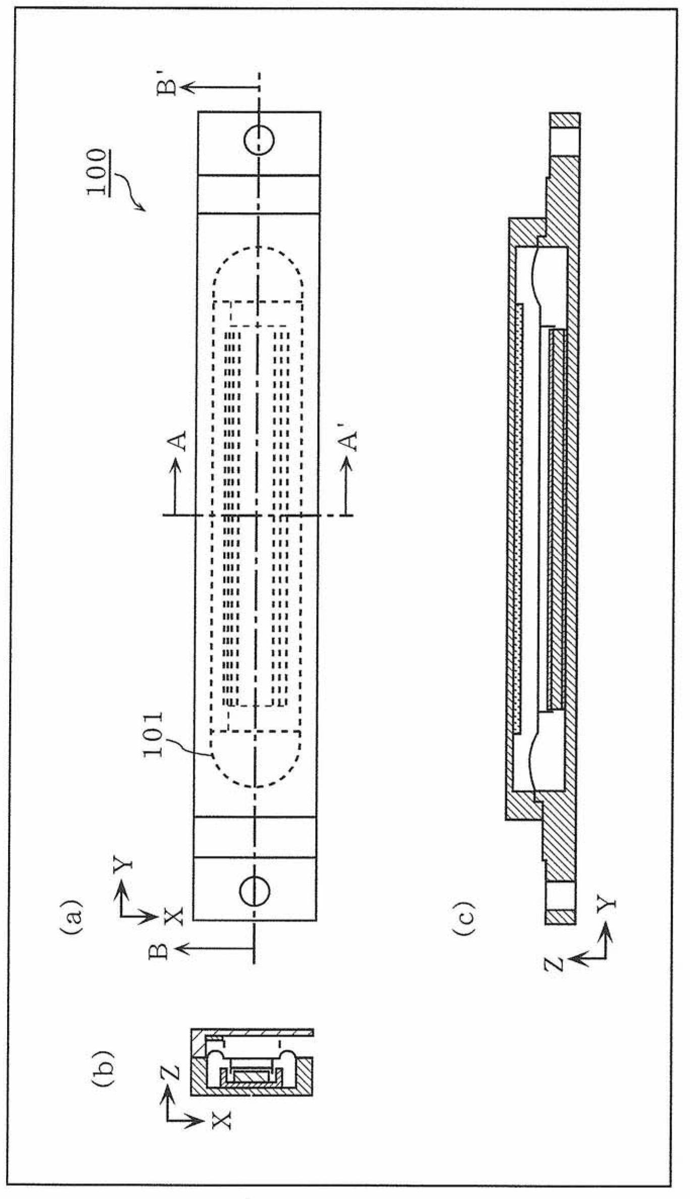
[0051] figure 1 It is a figure which shows the outline of the structure of the speaker 100 in Embodiment 1.
[0052]figure 1 (a) is a top view of the speaker 100, figure 1 (b) is shown in figure 1 The A-A' cross-section diagram of (a), figure 1 (c) is shown in figure 1 The diagram of the BB' section of (a).
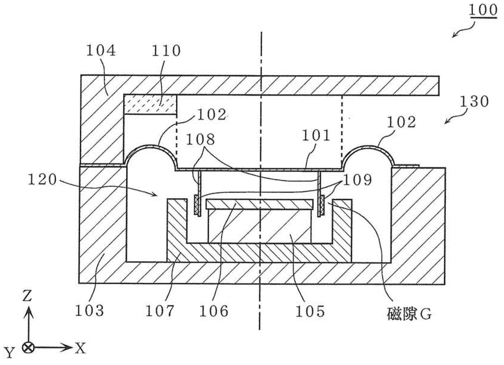
[0053] figure 2 Yes figure 1 (b) is an enlarged view of the AA' cross section of the speaker 100 shown.
[0054] like figure 2 As shown, the speaker 100 has a diaphragm 101 having a connecting portion 102 , a frame 103 , a cover member 104 , a magnetic circuit 120 having a magnet 105 and a yoke 107 , a voice coil 109 , and a spacer 110 .
[0055] In addition, a metal plate 106 is provided on the magnet 105 , and a voice coil 109 is connected to the diaphragm 101 via a voice coilbobbin 108 .
[0056] The vibrating plate 101 is arranged above the magnetic circuit 120, and at lea...
Embodiment approach 2
[0132] Hereinafter, speaker 200 in Embodiment 2 will be described.
[0133] Figure 9 It is a figure which shows the outline of the structure of the speaker 200 in Embodiment 2.
[0134] Figure 9 (a), (b), (c), and (d) are a plan view, a front view, a rear view, and a right side view of the speaker 200, respectively.
[0135] Figure 10 It is an enlarged view of the AA' cross section of the speaker 200 according to the second embodiment.
[0136] Such as Figure 10 As shown, the speaker 200 has: a vibration plate 201 having a connecting portion 202, a frame 203, a spacer 204, a cover member 205, magnets 206 and 207 magnetized in opposite directions, yokes 208 and 209, a voice coil 210, and Brake cloth 211. Speaker 200 differs from speaker 100 of Embodiment 1 mainly in the following five points.
[0137] (1) The magnetic circuit 220 of the speaker 200 is constituted by the magnets 206 and 207 and the yokes 208 and 209 arranged above and below the diaphragm 201 .
[013...
PUM
Abstract
A speaker (100, 200) comprises: a magnetic circuit (120, 220); a frame (103, 203); a coil (109, 210); a diaphragm (101, 201) having a connector (102, 202) for connecting the diaphragm (101, 201) and the frame (103, 203) so that the diaphragm (101, 201) can oscillate in the up-down direction in relation to the frame; and a cover member (104, 205) connected to one lateral end of the frame (103, 203), the lateral direction being the direction orthogonal to the up-down direction, the cover member being disposed so as to cover the diaphragm (101, 201) from above, and the cover member forming an opening (130, 230) for emitting sound between the two lateral ends of the frame (103, 203). The cover member (104, 205) has, on the closed end side, a spacer (110, 204) for reducing the volume of the space on the closed end side above the diaphragm (101, 201) and below the cover member (104, 205).
Description
technical field [0001] The present invention relates to a loudspeaker, in particular to a frame structure of a thinned loudspeaker. Background technique [0002] In recent years, with the popularization of so-called high-definition video and wide-screen TVs, the screens of TVs are becoming normal horizontally wide TVs. In addition, a thin TV is expected as a whole of the TV. [0003] Speaker units for thin TVs (hereinafter referred to as "speakers") are required to be narrower in width and thickness as TVs become thinner and the width of the casing around the display becomes thinner. In addition, at the same time as the image quality of the screen is improved, the sound quality of the output sound is also required to be improved. [0004] In addition to speakers for thin TVs, speakers for small wireless devices have been proposed that are housed in a narrow space and that can radiate sound forward (see Patent Document 1). [0005] In small wireless devices, it is necessar...
Claims
Application Information
Patent Timeline
Application Date:The date an application was filed.
Publication Date:The date a patent or application was officially published.
First Publication Date:The earliest publication date of a patent with the same application number.
Issue Date:Publication date of the patent grant document.
PCT Entry Date:The Entry date of PCT National Phase.
Estimated Expiry Date:The statutory expiry date of a patent right according to the Patent Law, and it is the longest term of protection that the patent right can achieve without the termination of the patent right due to other reasons(Term extension factor has been taken into account ).
Invalid Date:Actual expiry date is based on effective date or publication date of legal transaction data of invalid patent.

