Sheet metal component punching mould

A technology of sheet metal parts and molds, applied in the field of sheet metal parts processing equipment, can solve the problems of low processing efficiency and achieve the effect of improving precision and novel structural design

Inactive Publication Date: 2012-10-03
WUHU HANGUANG STEREO PARKING EQUIP
View PDF4 Cites 9 Cited by
  • Summary
  • Abstract
  • Description
  • Claims
  • Application Information

AI Technical Summary

Problems solved by technology

[0002] The existing sheet metal blanking machine mold has a relatively simple structure and low processing efficiency

Method used


Image

  • Sheet metal component punching mould

Examples


Embodiment Construction

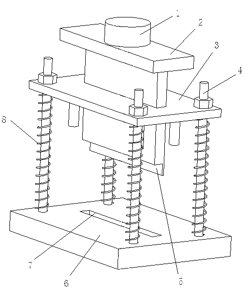
[0012] see figure 1 , a sheet metal blanking die, with an upper template 3 and a lower template 6 arranged longitudinally.

[0013] The lower template 6 is provided with four guide pillars 4 arranged in a square shape. The top of the guide pillars 4 passes through the upper template 3 and is fixed with nuts. The guide pillars 4 are sleeved with springs 8 .

[0014] The upper template 3 is fixed with a punching block 2 , the top of the punching block 2 is connected to the cylinder 1 , and the bottom is provided with an L-shaped knife edge 5 , and the cylinder 1 and the L-shaped knife edge 5 are respectively placed on the upper and lower sides of the upper template 3 .

[0015] The lower template 6 is provided with a square groove 7 , and the L-shaped knife edge 5 extends into the square groove 7 when the upper template 3 falls.

[0016] The above content is only an example and description of the structure of the present invention, and those skilled in the art can make various ...


PUM


Abstract

The invention relates to a sheet metal component punching mould belonging to the technical field of sheet metal component processing equipment. The sheet metal component punching mould comprises an upper mould plate and a lower mould plate, wherein the upper mould plate and the lower mould plate are longitudinally distributed; four guide pillars distributed in a square shape are arranged on the lower mould plate; the tops of the guide pillars penetrate through the upper mould plate and are fixed by using nuts; springs are sleeved on the guide pillars; a punching block is fixed on the upper mould plate; the top of the punching block is connected with an air cylinder, and the bottom of the punching block is provided with an L-shaped tool edge; the air cylinder and the L-shaped tool edge are respectively arranged at the upper side and the lower side of the upper mould plate; a square groove is arranged on the lower mould plate; and the L-shaped tool edge stretches into the square groove when the lower mould plate is descended. The sheet metal component punching mould has novel structural design; in the invention, the descending of the upper mould plate is controlled through the air cylinder, thereby realizing the punching operation of a sheet metal component; and the control of the descending direction of the upper mould plate is realized through the guide pillars and the springs, thereby enhancing the accuracy of punching processing.

Description

technical field [0001] The invention relates to a blanking die for sheet metal parts, belonging to the technical field of sheet metal parts processing equipment. Background technique [0002] The existing sheet metal part blanking machine die has a relatively simple structure and low processing efficiency. SUMMARY OF THE INVENTION [0003] In view of the above problems existing in the prior art, the present invention provides a sheet metal blanking die with high processing efficiency. [0004] The technical scheme adopted in the present invention is as follows: [0005] The punching die for sheet metal parts is characterized in that it has an upper template and a lower template arranged in a longitudinal direction, [0006] The lower formwork is provided with four guide posts arranged in a square shape, the top of the guide posts passes through the upper formwork and is fixed with nuts, and the guide posts are sleeved with springs; [0007] The upper template is fixed w...

Claims


Application Information

Patent Timeline
Patent Type & Authority Applications(China)
IPC IPC(8): B21D28/14
Inventor 张华祥杜伟陈薇杨平
Owner WUHU HANGUANG STEREO PARKING EQUIP
Why Eureka
Try Eureka