Precise positioning and punching equipment for fishing net silk frame

A precise positioning and punching technology, used in positioning devices, metal processing equipment, feeding devices, etc., can solve problems such as insufficient uniformity and aesthetics, and inability to accurately position

Active Publication Date: 2021-07-06
刘俊
View PDF5 Cites 1 Cited by
  • Summary
  • Abstract
  • Description
  • Claims
  • Application Information

AI Technical Summary

Problems solved by technology

[0004] In order to overcome the shortcomings of inaccurate positioning and insufficient uniformity and aesthetics, the technical problem of the present invention is to provide a precise positioning for fishing net wire frames that can accurately locate, ensure the uniformity and aesthetics of punching shapes, and improve the factory rate. punching equipment

Method used


Image

  • Precise positioning and punching equipment for fishing net silk frame
  • Precise positioning and punching equipment for fishing net silk frame
  • Precise positioning and punching equipment for fishing net silk frame

Examples


Embodiment 1

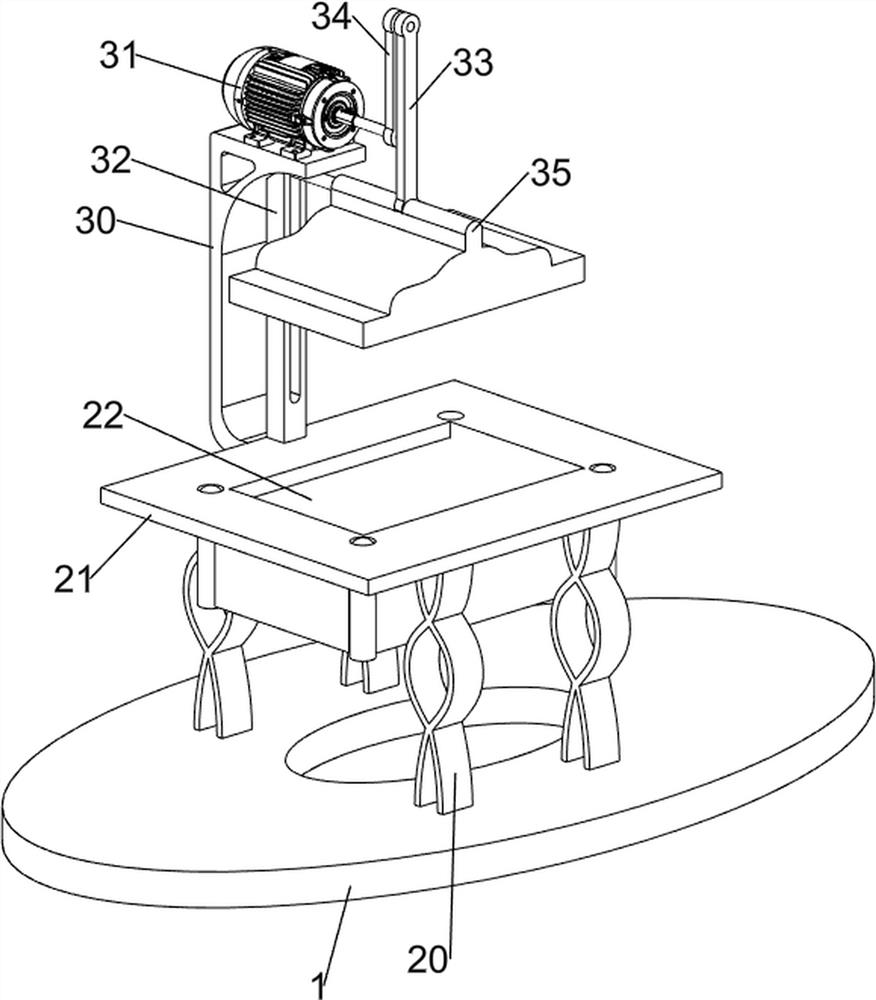
[0067] A punching equipment used for precise positioning of fishnet wire frames, such as figure 1 As shown, it includes a base 1 , a supporting mechanism 2 and a punching mechanism 3 , the upper side of the base 1 is connected with the supporting mechanism 2 , and the rear side of the supporting mechanism 2 is connected with the punching mechanism 3 .

[0068] When the device needs to be used, the user can place the raw material plate on the upper side of the support mechanism 2 to achieve the purpose of supporting the raw material plate and facilitating subsequent operations, start the punching mechanism 3, and the punching mechanism 3 rotates forward, and then makes The punching mechanism 3 moves downwards, and the punching mechanism 3 then moves upwards to achieve the purpose of stamping the raw material plate. After the operation is completed, the user can close the punching mechanism 3, remove the punched raw material plate, and use it again. , repeat the operation.

Embodiment 2

[0070] On the basis of Example 1, such as figure 2 As shown, the support mechanism 2 includes a support leg 20 and a placement platform 21, two support legs 20 are connected to the front and rear sides of the top of the base 1, and a placement platform 21 is connected between the tops of the support legs 20, and a recess is provided on the placement platform 21. Slot 22.

[0071] When the device needs to be used, the user can place the raw material board on the upper side of the placing table 21 to achieve the purpose of supporting the raw material board and facilitating the follow-up operation, and continue the follow-up operation. When using it again, repeat the operation.

[0072] Such as figure 2As shown, the punching mechanism 3 includes a support plate 30, a servo motor 31, a first slide rail 32, a first crank 33, a second crank 34 and a punching block 35, and the rear side of the placing table 21 is connected with a support plate 30 to support A servomotor 31 is con...


PUM


Abstract

The invention relates to punching equipment, in particular to precise positioning and punching equipment for a fishing net silk frame. According to the precise positioning and punching equipment for the fishing net silk frame, precise positioning can be achieved, uniformity and attractiveness of punching are guaranteed, and the factory rate is increased. According to the technical scheme, the precise positioning and punching equipment for the fishing net wire frame comprises a supporting mechanism and a punching mechanism, wherein the top side of a base is connected with the supporting mechanism; and one side of the supporting mechanism is connected with the punching mechanism. Through cooperation of supporting legs and a placing table, the purposes of supporting a raw material plate and facilitating follow-up operation are achieved.

Description

technical field [0001] The invention relates to a punching device, in particular to a punching device for precise positioning of a fishing net wire frame. Background technique [0002] Fishing nets, or "fishing nets", are indispensable fishing tools for fishery production. Coastal fishermen first used simple nets to fish on the seashore. Shallow sea fishing nets such as lift nets and stick nets appeared in the Ming Dynasty. Inland river fishermen mostly fish with small fishing gear. The main fishing gear used in fishery production are lift net, stick net, push net, arch net, ground net, plug net, grab net, stick net, pull net, flow net, etc. Nets, trawling, throwing nets, spinning nets, casting nets, fishing hooks, clam fishing poles, fishing nets, foils, river seines, rowing nets, scooping nets, whirling nets, hanging nets, foil nets, crab pots and crab bowls Among them, pull nets and drift nets are often used for distant sea fishing, and sticky nets are mostly used for in...

Claims


Application Information

Patent Timeline
IPC IPC(8): B21D28/02B21D28/04B21D43/02
CPCB21D28/02B21D28/04B21D43/02Y02A40/81
Inventor 不公告发明人
Owner 刘俊
Why Eureka
Try Eureka