Pipe fitting drilling device

A technology of drilling device and pipe fittings, applied in the field of pipe fittings processing, can solve the problems of single setting mode, reduced processing efficiency, inability to realize multiple groups of drilling operations, etc. The effect of the hole punch effect

Inactive Publication Date: 2018-11-13
广州吉和电子商务有限公司
View PDF3 Cites 2 Cited by
  • Summary
  • Abstract
  • Description
  • Claims
  • Application Information

AI Technical Summary

Problems solved by technology

[0002] Carbide pipe fittings are widely used in modern industrial production. Carbide pipe fittings need to be punched during production, while the traditional punching device has a single setting mode, and requires too much manpower to use, and cannot Realize multiple groups of drilling operations on the same straight line, which greatly reduces the processing efficiency, has great disadvantages, and needs to be improved

Method used


Image

  • Pipe fitting drilling device
  • Pipe fitting drilling device
  • Pipe fitting drilling device

Examples


Embodiment Construction

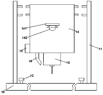
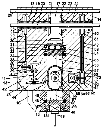
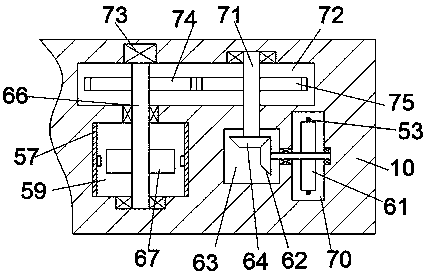
[0021] Such as Figure 1-3As shown, a pipe fitting drilling device of the present invention includes a machine base 10, a support 11 symmetrically arranged on the top end surface of the machine base 10, and a sliding frame 14 arranged between the two left and right supports 11. The bottom of the sliding frame 14 is fixed with an assembly block 15, and the assembly block 15 is provided with a downward sliding groove 151, and the first sliding block 69 is installed slidingly in the sliding groove 151, and the first sliding block 69 A first driving machine 48 is arranged in the end surface of the bottom, and the bottom of the first driving machine 48 is power-connected with a drilling head 49. The sliding frame 14 is provided with a sliding chamber 17 that communicates with the sliding groove 151 and extends upward. , the sliding seat 57 located above the first sliding block 69 is installed slidingly in the sliding chamber 17, the first rotating chamber 59 passing through the fro...


PUM


Abstract

The invention discloses a pipe fitting drilling device. The pipe fitting drilling device comprise a machine base, supports which are laterally symmetrically arranged on the top end surface of the machine base and a sliding rack which is arranged between the two supports; an assembly block is fixedly arranged on the bottom part of the sliding rack; a sliding groove of which the end opening is downward is formed in the assembly block; a first sliding block is slidably arranged in the sliding groove; a first driver is arranged in the bottom end surface of the first sliding block; the bottom partof the first driver is in power connection with a drill bit; a sliding cavity which communicates with the sliding groove and extends upwards is formed in the sliding rack; a sliding base which is located above the first sliding block is slidably arranged in the sliding cavity; a first rotation cavity which is front-back through is formed in the sliding base; a second rotation cavity which extendsleftwards and rightwards is formed in a part, which is on the rear side of the sliding cavity, of the sliding rack; and a first rotary shaft which extends frontwards and backwards is arranged betweenthe second rotation cavity and the sliding cavity.

Description

technical field [0001] The invention relates to the technical field of pipe fitting processing, in particular to a pipe fitting drilling device. Background technique [0002] Carbide pipe fittings are widely used in modern industrial production. Carbide pipe fittings need to be punched during production, while the traditional punching device has a single setting mode and requires too much manpower to use. At the same time, it cannot Realizing multiple groups of drilling operations on the same straight line greatly reduces the processing efficiency, has relatively large disadvantages, and needs to be improved. Contents of the invention [0003] The technical problem to be solved by the present invention is to provide a pipe drilling device, which can solve the above-mentioned problems in the prior art. [0004] The present invention is achieved through the following technical solutions: comprising a machine base, a bracket arranged symmetrically on the top end surface of t...

Claims


Application Information

Patent Timeline
IPC IPC(8): B23Q5/28B23B47/20B23B41/00
CPCB23B41/00B23Q5/28
Inventor 余小兰
Owner 广州吉和电子商务有限公司
Why Eureka
Try Eureka