Pinch roll mechanism

A technology of pinch rollers and racks, which is applied in metal processing equipment, feeding devices, manufacturing tools, etc., can solve the problems of wasteful cost and complicated structure.

Active Publication Date: 2012-10-03
CHINA NAT HEAVY MACHINERY RES INSTCO
View PDF6 Cites 16 Cited by
  • Summary
  • Abstract
  • Description
  • Claims
  • Application Information

AI Technical Summary

Problems solved by technology

In the straightening machine device, in order to ensure the reliability and stability of feeding, there are feeding pinch rollers and output pinch rollers respectively installed between the loading and unloading platform and the main machine, and the feeding pinch rollers will feed the material The steel pipe on the stand is sent to the main machine of the straightening machine, and the output pinch roller will send the steel pipe out of the main machine of the straightening machine. The traditional structure is to install several sections of lifting rollers on the loading and unloading table, and drive the rollers through the motor. Rotating to send materials in or out, such a structure is cumbersome and costly

Method used


Image

  • Pinch roll mechanism
  • Pinch roll mechanism

Examples


Embodiment Construction

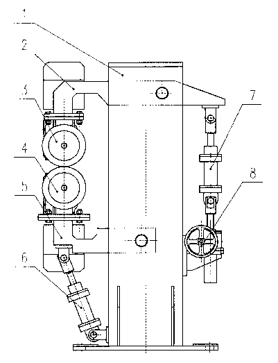
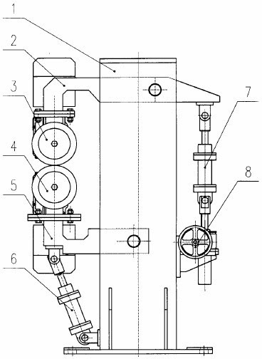
[0012] like figure 1 As shown, the lower hydraulic cylinder 6 and the elevator 8 are respectively installed at the bottom of both sides of the frame 1, the lower hydraulic cylinder 6 is hinged with the frame 1 through the bottom of the cylinder, and the elevator 8 is slidingly connected with the frame 1.

[0013] The lower swing rod 5 is L-shaped, one end of which is pinned to the lower part of the frame through a pin shaft, and the lower swing rod can rotate around this fixed point; The transmission device 4 is fixedly connected.

[0014] The upper swing link 2 is also L-shaped, and the length of its upper side is greater than the width of the frame 1. The long side of the upper swing link 2 is pinned to the upper part of the frame 1 through a pin shaft, and the upper swing link 2 can rotate around this fixed point; One end of the rod 2 is fixedly connected with the upper roller transmission device 3, the other end is hinged with the upper hydraulic cylinder 7, and the cylin...


PUM


Abstract

The invention relates to the field of metallurgical mechanical equipment, in particular to a pinch roll mechanism. The pinch roll mechanism at least comprises a rack, an upper oscillating rod, an upper roller driving device, a lower roller driving device, a lower oscillating rod, a lower hydraulic cylinder, an upper hydraulic cylinder and a lifer, and is characterized in that the upper oscillating rod is L-shaped, the length of the upper edge of the upper oscillating rod is larger than the width of the rack, the long edge of the upper oscillating rod is in pin joint with the upper part of the rack through a pin shaft, one end of the upper oscillating rod is fixedly connected with the upper roller driving device, and the other end of the upper oscillating rod is hinged with the upper hydraulic cylinder; the bottom part of the upper hydraulic cylinder is hinged with the lifter, and the lifter is in slide connection with the rack; the lower oscillating rod is in pin joint with the lower part of the rack through a pin shaft, one end of the lower oscillating rod is fixedly connected with the lower roller driving device, the lower oscillating rod is also hinged with the lower hydraulic cylinder, and the bottom part of the lower hydraulic cylinder is fixedly connected with the rack; and the axial lines of the two rollers in the upper roller driving device and the lower roller driving device are located on the same straight line. The pinch roll mechanism provided by the invention can be used for adjusting the openness of the upper roller through the lifter and clamping and loosening the rollers through the upper and lower hydraulic cylinders.

Description

technical field [0001] The invention relates to the field of metallurgical machinery and equipment, and relates to a pinch roller mechanism. Background technique [0002] The pinch roller mechanism is mainly used for clamping and feeding metal strips, tubes, rods and shapes. In the straightening machine device, in order to ensure the reliability and stability of feeding, there are feeding pinch rollers and output pinch rollers respectively installed between the loading and unloading platform and the main machine, and the feeding pinch rollers will feed the material The steel pipe on the stand is sent to the main machine of the straightening machine, and the output pinch roller will send the steel pipe out of the main machine of the straightening machine. The traditional structure is to install several sections of lifting rollers on the loading and unloading table, and drive the rollers through the motor. Rotating to send materials in or out, such a structure is both loaded ...

Claims


Application Information

Patent Timeline
Patent Type & Authority Applications(China)
IPC IPC(8): B21D43/08
Inventor 张超常瑜汪恩辉黄维勇陈峰左雁冰何潜刘杰高聪敏薛红卫
Owner CHINA NAT HEAVY MACHINERY RES INSTCO
Why Eureka
Try Eureka