Multifunctional reinforcing steel bar automatic hoop-bending machine bending from two ends of reinforcing steel bar

A multi-functional, hoop bending machine technology, applied in the field of automatic bar hoop bending machines, can solve the problems of inability to quickly bend stirrup products with hooks at both ends, inability to bend steel bars, and high production costs, achieving simple structure and wide production range. , the effect of low cost

Active Publication Date: 2012-10-03
TJK MACHINERY TIANJIN
View PDF10 Cites 13 Cited by
  • Summary
  • Abstract
  • Description
  • Claims
  • Application Information

AI Technical Summary

Problems solved by technology

[0004] The above-mentioned prior art steel bar automatic bending machine has the following defects: the prior art steel bar automatic bending machine can only be bent into various shapes from one end of the steel bar to the steel bar along the upstream moving direction at different positions, such as triangle, square, Round and other shapes, but the steel bar cannot be bent from the other end of the steel bar, that is, the existing automatic steel bar bending machine cannot pro

Method used


Image

  • Multifunctional reinforcing steel bar automatic hoop-bending machine bending from two ends of reinforcing steel bar
  • Multifunctional reinforcing steel bar automatic hoop-bending machine bending from two ends of reinforcing steel bar
  • Multifunctional reinforcing steel bar automatic hoop-bending machine bending from two ends of reinforcing steel bar

Examples


Example Embodiment

[0020] The embodiments of the present invention will be described in further detail below with reference to the accompanying drawings.

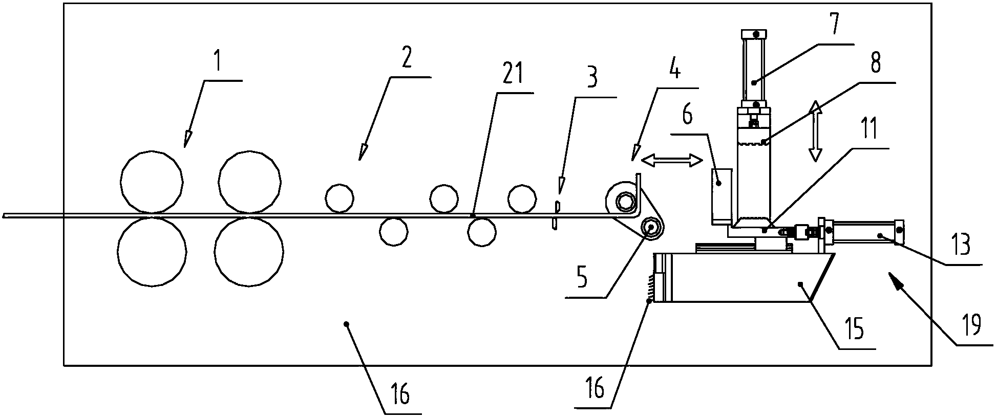
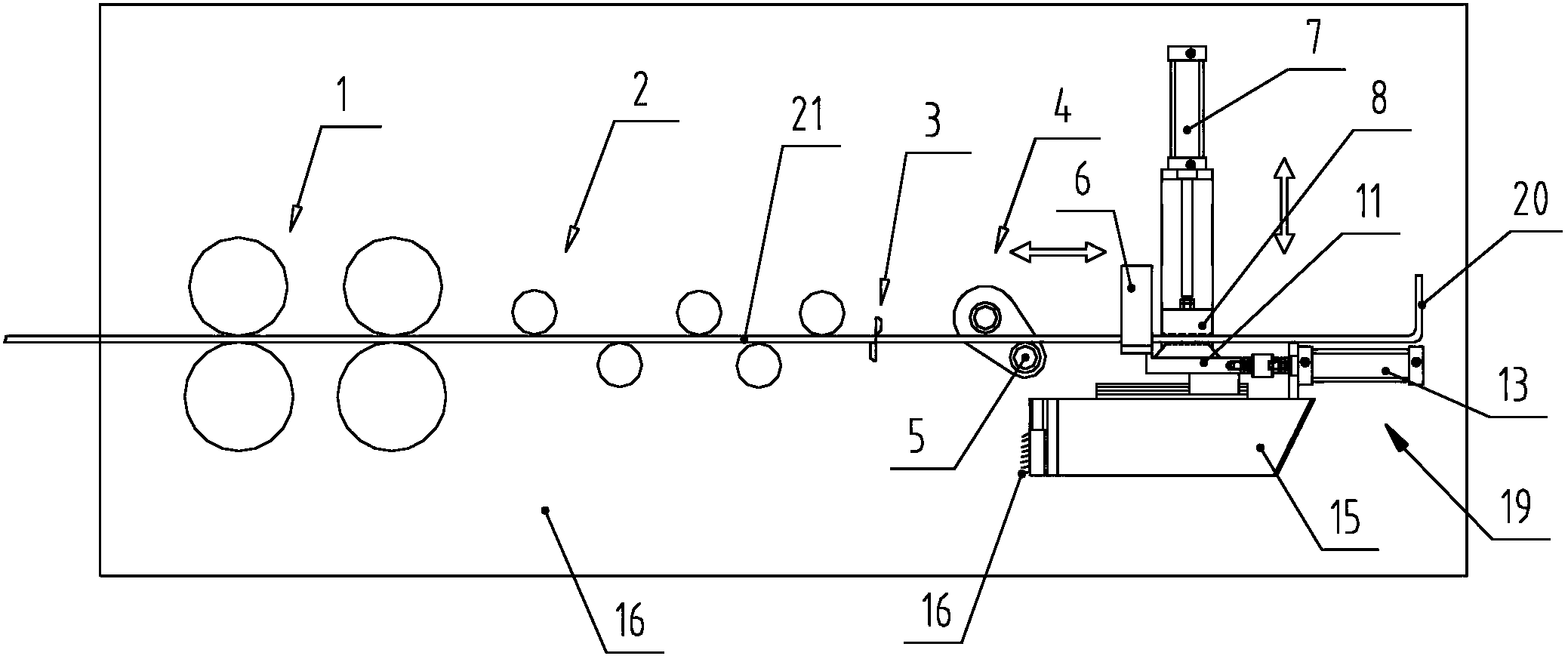
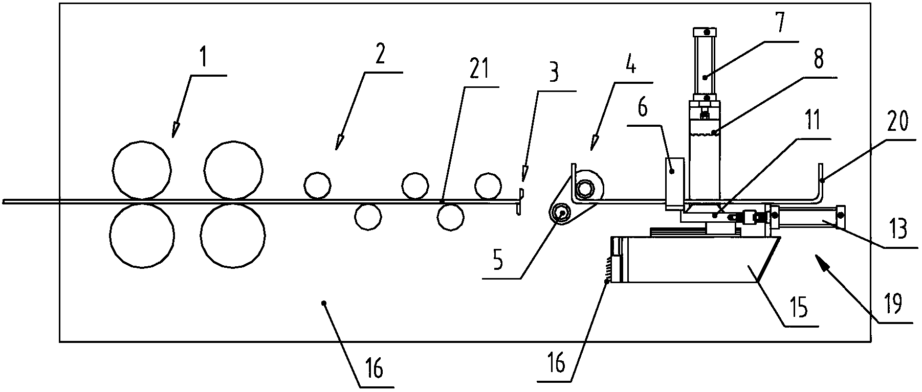
[0021] As shown in the figure, the present invention provides a multifunctional automatic steel bar bending machine that is bent from both ends of the steel bar. The multifunctional automatic steel bar bending machine includes: a frame 16; the frame 16 moves upstream along the steel bar 21 In the axial direction, the traction mechanism 1, the straightening mechanism 2, the shearing mechanism 3, and the bidirectional bending mechanism 4 are sequentially arranged.

[0022] The frame 16 upstream of the two-way bending mechanism 4 is also provided with a multifunctional mechanism 19 for bending the steel bar from the cut end. The multifunctional mechanism 19 includes: clamping the steel bar 21 and transferring the cut end of the steel bar The two-way bending mechanism 4 to its downstream position is a pressing and transferring mechanism for bending, a...


PUM


Abstract

The invention discloses a multifunctional reinforcing steel bar automatic hoop-bending machine bending from the two ends of a reinforcing steel bar. The multifunctional reinforcing steel bar automatic hoop-bending machine comprises a machine frame, wherein a traction mechanism, a straightening mechanism, a shearing mechanism and a bidirectional bending mechanism are axially arranged on the machine frame along the upstream of the reinforcing steel bar sequentially; a multifunctional mechanism is also arranged on the machine frame on the upstream of the bidirectional bending mechanism; the multifunctional mechanism comprises a compression moving mechanism, a material-pushing mechanism and an overall retraction mechanism; the material-pushing mechanism is used for pushing a hoop bar which is formed in a bending way; and the overall retraction mechanism is used for pulling the compression moving mechanism and the material-pushing mechanism into the inner side of a machine shell panel or pushing the compression moving mechanism and the material-pushing mechanism to a working position. The multifunctional reinforcing steel bar automatic hoop-bending machine has the beneficial effects that the other end of the reinforcing steel bar which is sheared by the shearing mechanism can be bent, long hoop bar products with hooks at the two ends can be bent rapidly and at one time, the requirement of production is met, and the production efficiency is high. The multifunctional reinforcing steel bar automatic hoop-bending machine is simple in structure, low in cost, high in adaptability, wide in production range, and has complete functions.

Description

technical field [0001] The invention relates to an automatic hoop bending machine for steel bars, in particular to a multifunctional automatic hoop bending machine for steel bars that bends from both ends of the steel bars. Background technique [0002] The steel bar automatic bending machine is a steel bar automatic processing equipment that bends straight steel bars into stirrups of a certain shape. With the rapid development of economic construction, the automatic hoop bending machine for steel bars has been widely used. The automatic hoop bending machine for steel bars in the prior art includes: a traction mechanism, a straightening mechanism, a shearing mechanism and a bending mechanism arranged in sequence according to the axis. [0003] The production process of the above-mentioned prior art steel bar automatic bending hoop machine is: the traction mechanism pulls and moves the coiled steel bar to the upstream direction; the straightening mechanism straightens the be...

Claims


Application Information

Patent Timeline
IPC IPC(8): B21F1/00B21F23/00
Inventor 陈振东
Owner TJK MACHINERY TIANJIN
Why Eureka
Try Eureka