LED light bar and side-entry backlight module using the light bar

A technology of LED light bar and side-type backlight, which is applied in the light guide, optics, light guide and other directions of the lighting system, which can solve the problems of affecting the display effect and lengthening of the dark area, and achieve the effect of increasing the light irradiation range and improving the quality

Active Publication Date: 2014-10-15
TCL CHINA STAR OPTOELECTRONICS TECH CO LTD
View PDF5 Cites 0 Cited by
  • Summary
  • Abstract
  • Description
  • Claims
  • Application Information

AI Technical Summary

Problems solved by technology

When it is required to use dynamic scanning (scanning) mode to achieve 3D, it is necessary to use a micro-structured light guide plate that can constrain light. At this time, the phenomenon of dark areas left in the corner will become more serious, and the length of dark areas will be greatly increased, seriously affecting display effect

Method used


Image

  • LED light bar and side-entry backlight module using the light bar
  • LED light bar and side-entry backlight module using the light bar
  • LED light bar and side-entry backlight module using the light bar

Examples


Embodiment Construction

[0024] In order to further illustrate the technical means adopted by the present invention and its effects, the following describes in detail in conjunction with preferred embodiments of the present invention and accompanying drawings.

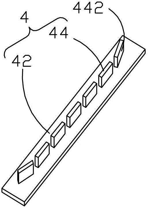
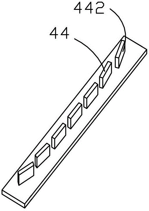
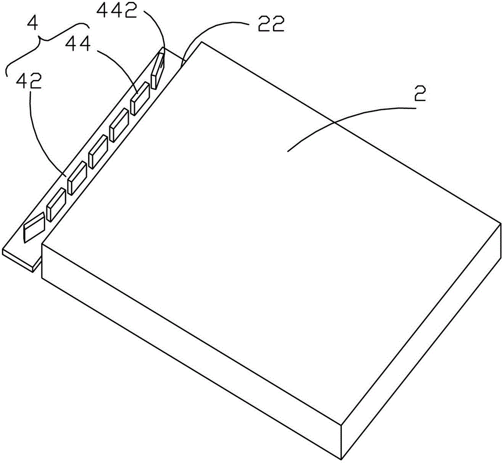
[0025] Such as figure 1 As shown, the present invention provides an LED light bar 4, comprising: a PCB board 42 and several LED lamps 44 installed and electrically connected to the PCB board 42, each LED lamp 44 has a light-emitting surface 442, the The light-emitting surface 442 is perpendicular to the PCB board 42, the several LED lights 44 are arranged in sequence and their light-emitting surfaces 442 are located on the same side of the PCB board 42, the light-emitting surfaces 442 of the middle LED lights 44 are arranged in a straight line, and the LED lights 44 at both ends The light-emitting surface 442 is deflected in a direction away from the light-emitting surface 442 of the middle LED lamp 44 to increase the light irradiation range o...


PUM


Abstract

An LED light strip (4) comprises a PCB board (42) and a plurality of LED lamps (44) installed on and electrically connected to the PCB board (42). Each LED lamp (44) has a light-emitting surface, and the light-emitting surface is perpendicular to the PCB board (42). The light-emitting surfaces of the LED lamps (44) on two ends are disposed in a way of tilting away from the light-emitting surface of the LED lamp (4) at the middle, so as to increase a light radiation area of the LED light strip (4). Also provided is a side-type backlight module using the LED light strip (4). By tilting the light-emitting surfaces of the LED lamps (44) on two ends of the LED light strip (4), an angle is formed between the light-emitting surfaces of the LED lamps (44) and a light incident surface of a light guide plate, which increases a light radiation area of the LED light strip (4), so that the light of the LED lamps (44) is irradiated onto corners of the light guide plate. In this way, dark zones at the corners of the light guide plate are eliminated effectively, and quality of the backlight module is improved.

Description

technical field [0001] The invention relates to the field of liquid crystal display, in particular to an LED light bar and a side-entry backlight module using the light bar. Background technique [0002] A liquid crystal display (LCD, Liquid Crystal Display) has many advantages such as a thin body, power saving, and no radiation, and has been widely used. Most of the liquid crystal display devices currently on the market are backlight liquid crystal display devices, which include a liquid crystal panel and a backlight module. The working principle of the liquid crystal panel is to place liquid crystal molecules between two parallel glass substrates, and control the liquid crystal molecules to change direction by electrifying the glass substrates, refracting the light from the backlight module to produce a picture. Since the liquid crystal panel itself does not emit light, the light source provided by the backlight module is needed to display images normally. Therefore, the ...

Claims


Application Information

Patent Timeline
Patent Type & Authority Patents(China)
IPC IPC(8): F21S4/00F21S8/00F21V13/00F21V19/00F21Y101/02
CPCG02B6/0068G02F1/1335G02B6/0091G02B6/0073
Inventor 黄建发
Owner TCL CHINA STAR OPTOELECTRONICS TECH CO LTD
Why Eureka
Try Eureka