
Joint estimation method for azimuth angle and elevation angle of signal on basis of L-type sensor array

A sensor array and azimuth technology, applied in the field of signal processing, can solve the problems of high computational complexity of two-dimensional wave arrival, inability to apply real-time environment, and inability to provide pairing results, etc.

Active Publication Date: 2014-03-12
RES INST OF XIAN JIAOTONG UNIV & SUZHOU
View PDF3 Cites 0 Cited by
  • Summary
  • Abstract
  • Description
  • Claims
  • Application Information

AI Technical Summary

Problems solved by technology

[0005] The purpose of the present invention is to provide a method for joint estimation of signal azimuth and elevation based on an L-shaped sensor array, which solves the problem that the two-dimensional direction of arrival estimation in the prior art has a large computational complexity, often cannot provide correct matching results, and cannot be applied problems in real-time environments

Method used


Image

  • Joint estimation method for azimuth angle and elevation angle of signal on basis of L-type sensor array
  • Joint estimation method for azimuth angle and elevation angle of signal on basis of L-type sensor array
  • Joint estimation method for azimuth angle and elevation angle of signal on basis of L-type sensor array

Examples


Embodiment

[0067] Direction of Arrival estimation combining azimuth and elevation angles according to an embodiment of the present invention will be described in detail below.

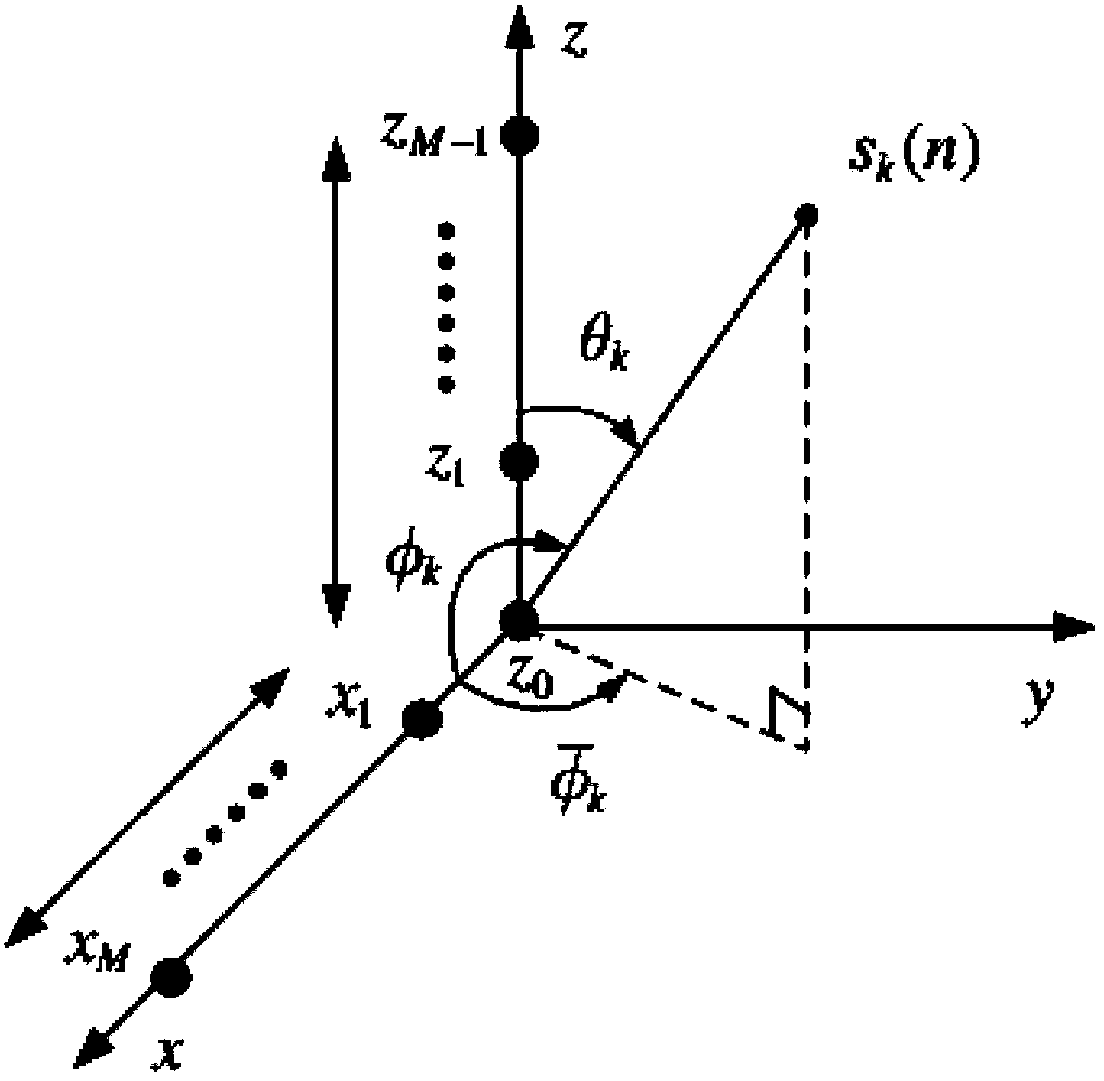
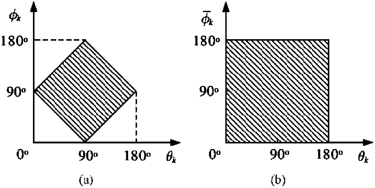
[0068] Such as figure 1 As shown, the L-shaped sensor array is placed on the x-z plane and consists of two uniform linear arrays. Each uniform linear array contains M omnidirectional sensors with a spacing of d. At the origin of the coordinate system z 0 The sensor at is used as a reference for each uniform line array, z 0 and x 1 The sensor spacing is also d. Assume p incoherent far-field narrowband signals {s k (n)}, wavelength λ, from different elevation and azimuth angles {θ k ,φ k} incident on the array. Such as figure 1 As shown, the elevation angle θ k and azimuth φ k Measured clockwise relative to the z-axis or x-axis, azimuthal projection Measured counterclockwise with respect to the x-axis in the x-y plane. Here 0°≤θ k ≤180°, 0°≤φ k ≤180°, The signal received by two uniform linear arrays...


PUM


Abstract

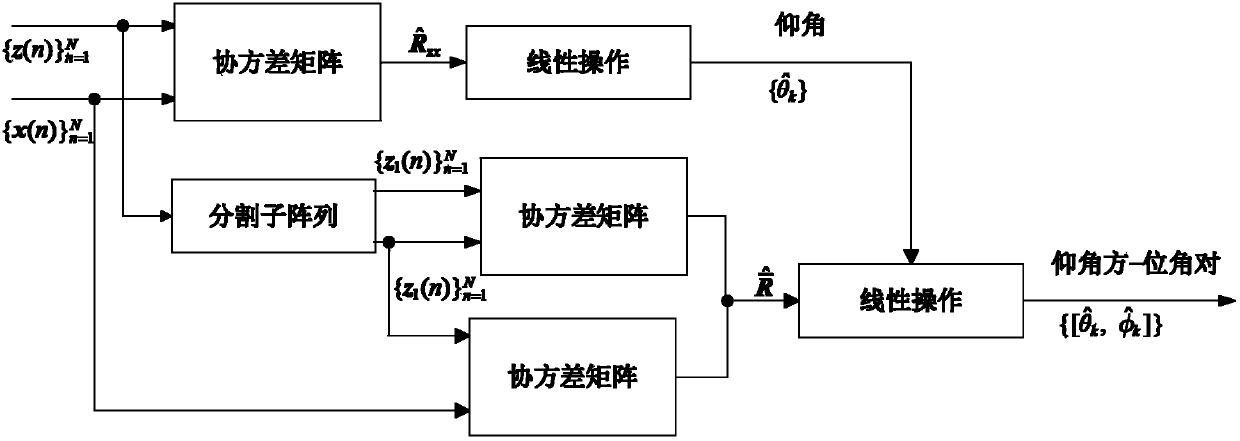
The invention discloses a joint estimation method for an azimuth angle and an elevation angle of a signal on the basis of an L-type sensor array. The joint estimation method is used for estimating a direction of arrival of an incidence signal emitted onto the L-type sensor array, wherein the L-type sensor array is placed on an x-z plane and is provided with two mutually vertical uniform linear arrays, and M omnidirectional sensors are equidistantly arranged in different spatial positions along a straight line on each of the uniform linear arrays. The joint estimation method is characterized by comprising the following steps: (1) estimating a covariance matrix of signals received by two rows of uniform linear arrays on x axis and z axis, and then obtaining an M*2M expanding cross covariance matrix by calculating according to the covariance matrix of the signals received by the two rows of uniform linear arrays; (2) cutting the uniform linear array on the z axis or x axis into two rows of non-coincident forward / backward sub-arrays, and then estimating the elevation angle by utilizing the expanding cross covariance matrix of data received by the two rows of uniform linear arrays according to a linear operation one-dimensional subspace method; and (3) estimating a corresponding azimuth angle by linearly operating by utilizing feasible regions of the azimuth angle and the elevation angle, the two rows of sub-arrays on the z axis or x axis and the cross covariance between one of the sub-array and the uniform linear array on the x axis or z axis.

Description

technical field [0001] The invention belongs to the technical field of signal processing, and in particular relates to a two-dimensional direction-of-arrival estimation, a segmented L-shaped array, which uses cross-correlation to estimate elevation angles, and then uses the estimated elevation angles to calculate corresponding azimuth angles. Background technique [0002] Array signal processing is an important branch of signal processing, which is closely related to parameter estimation, system identification, adaptive filtering, statistical signal processing, and matrix theory, and is used in radar, sonar, communication, seismic data processing, and medical imaging. It is widely used in many fields. Practical applications of array signal processing include radar, sonar, communications, etc., where the two-dimensional (2-D) direction of arrival (DOA) (eg, azimuth and elevation) of multiple incident signals must be estimated from numerous measurements. As the number of dime...

Claims


Application Information

Patent Timeline
Patent Type & Authority Patents(China)
IPC IPC(8): G01S3/14G01S3/12
Inventor 王光敏辛景民刘畅农郑南宁
Owner RES INST OF XIAN JIAOTONG UNIV & SUZHOU
Learn More