Electrowetting Display Panel

An electrowetting display and panel technology, applied in the direction of optical components, optics, instruments, etc., can solve the problems that cannot achieve full-color display effect, and achieve the effect of full-color display

Active Publication Date: 2014-10-15
BOE TECH GRP CO LTD
View PDF6 Cites 0 Cited by
  • Summary
  • Abstract
  • Description
  • Claims
  • Application Information

AI Technical Summary

Problems solved by technology

but if Figure 1B As shown, in the color display, although the ink layer 3 will expose most of the pixel areas when it shrinks, it will still cover a part of the pixel areas, so the full-color display effect that people are very satisfied with cannot be achieved.

Method used


Image

  • Electrowetting Display Panel
  • Electrowetting Display Panel
  • Electrowetting Display Panel

Examples


Embodiment Construction

[0036] In order to make the technical problems, technical solutions and advantages to be solved by the present invention clearer, the following will describe in detail with reference to the drawings and specific embodiments.

[0037] Embodiments of the present invention aim at the problem that the electrowetting display in the prior art cannot realize full-color display well, and provide an electrowetting display panel capable of realizing full-color display.

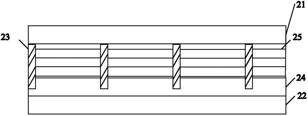
[0038] figure 2 It is a schematic structural diagram of an electrowetting display panel according to an embodiment of the present invention. The electrowetting display panel includes: a first substrate 21, a second substrate 22 opposite to the first substrate 21, and more than two substrates located on the second substrate 22. The barrier wall 23, more than two barrier walls 23 define more than two sub-pixels, the opaque insulating layer 24 located on the second substrate 22, the opaque insulating layer 24 includes a d...


PUM


Abstract

The present invention provides an electrowetting display panel, which includes a first substrate, a second substrate opposite to the first substrate, and more than two barrier walls on the second substrate, and the two or more barrier walls define two or more sub-pixels, an opaque insulating layer on the second substrate, the opaque insulating layer includes a dielectric layer and more than two opaque liquid units on the dielectric layer, the opaque The optical insulating layer can display black or white under the action of an electric field; two or more colored liquid units of different colors are respectively arranged between the opaque insulating layer and the first substrate corresponding to each sub-pixel, each colored liquid Cells are either conductive or polarized. The electrowetting display panel provided by the invention can realize full-color display.

Description

technical field [0001] The invention relates to the field of displays, in particular to an electrowetting display panel. Background technique [0002] The principle of the electrowetting (Electrowetting) display is to use the electrowetting phenomenon or the electrochemical capillary phenomenon. When the fluid is subjected to an electric field to change the surface free energy of the fluid, the distribution area of ​​the fluid is changed. The electrowetting phenomenon is the change of the contact angle between the electrolyte solution and the underlying insulating layer under the action of an electric field, that is, the phenomenon that the electrolyte solution shrinks or expands under the action of an electric field. The electrowetting display uses the principle of electrowetting phenomenon to display through electrodes to control ink expansion or contraction. Electrowetting display technology is more and more popular because of its characteristics of bistable display, goo...

Claims


Application Information

Patent Timeline
Patent Type & Authority Patents(China)
IPC IPC(8): G02B26/02
CPCG02B26/005G02B2207/115
Inventor 田肖雄薛建设
Owner BOE TECH GRP CO LTD
Why Eureka
Try Eureka