Electrowetting display device and display method

An electrowetting display and electrode technology, which is applied in static indicators, instruments, nonlinear optics, etc., can solve the problem of unable to achieve color display effect, and achieve the effect of realizing full color display and saving response time.

Active Publication Date: 2014-09-24
BOE TECH GRP CO LTD
View PDF4 Cites 0 Cited by
  • Summary
  • Abstract
  • Description
  • Claims
  • Application Information

AI Technical Summary

Problems solved by technology

[0007] Although electrowetting display technology has many advantages, it has not yet achieved a satisfactory color display effect.

Method used


Image

  • Electrowetting display device and display method
  • Electrowetting display device and display method
  • Electrowetting display device and display method

Examples


Embodiment 1

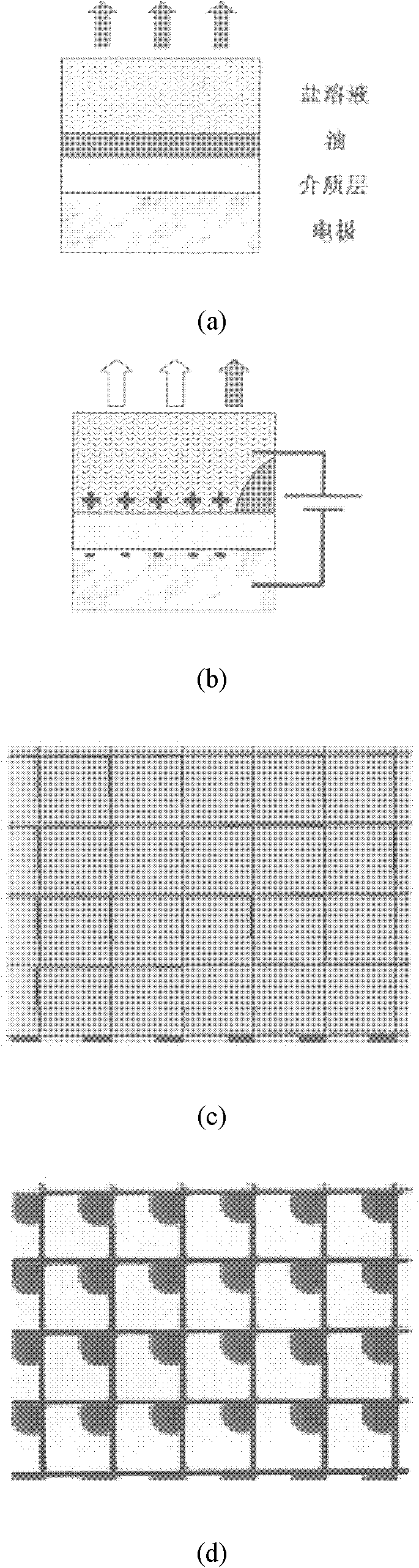
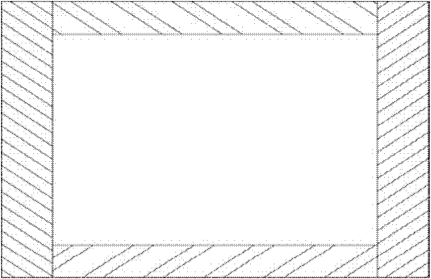
[0030] Such as figure 2 As shown, the display device of this embodiment includes an ink accommodating cavity, and the ink accommodating cavity is filled with inks of different colors, and the inks of different colors are incompatible with each other and are not soluble in the solution. The ink accommodating cavity is composed of an outer shell and an inner shell embedded in the outer shell. Both the outer shell and the inner shell are closed structures, and the ink is located in the cavity formed between the outer shell and the inner shell. The shapes of the outer shell and the inner shell are both cuboids. At this time, the ink holding cavity is divided into six cavities: upper, lower, left, right, front, and rear, and the six cavities are filled with different colors. ink.

[0031] The upper, lower, left, right, front and rear six cavities of the ink holding cavity are used to fill inks of different colors (the upper cavity is the display layer of the display device), so t...

Embodiment 2

[0036] Regarding the display device, it is conceivable that the upper cavity is the display surface, and the ink in the four cavities, front, rear, left, and right adjacent to the upper cavity can enter the display surface immediately when displayed, but the ink in the lower cavity needs to transition to a cavity in the middle. access to the display surface, which may adversely affect response time. Therefore, this embodiment is improved.

[0037] Such as Figure 5 As shown, a pipe communicating with the upper and lower cavities is set between the upper and lower cavities, so that the ink in the lower cavity can directly enter the upper cavity for display in one step without passing through the transition between the left and right cavities, thereby saving Response time.

Embodiment 3

[0039] In order to save response time, the lower cavity of this embodiment does not store ink, so that one pixel can display five colors at different times.

[0040] The types of colors that can be displayed by a pixel are determined by the amount of ink in the display device. Therefore, two or four colors can also be displayed. The display principle is similar to the six-color display in Embodiments 1 and 2.

[0041] Due to the incompatibility between the inks, each pixel of the present invention can also display the mixed colors of the inks, that is, two or more inks enter the display layer at the same time, for example, half of the red ink and the other half of the yellow ink can be realized. display, or 1 / 3 red ink, 2 / 3 yellow ink display. Monochrome display means that one pixel can realize one color at the same time, and two-color display is a mixed color of two colors at one pixel at the same time, and three or four colors can also be mixed. However, when applied to a d...


PUM


Abstract

The invention relates to the technical field of electrowetting display and discloses an electrowetting display device. The electrowetting display device comprises a printing ink containing cavity, wherein the cavity is filled with printing inks in different colours, the printing inks in different colours are not mutually dissolved and are not dissolved in salt solution around the printing inks. The invention also discloses a method for carrying out single-colour or double-colour display by utilizing the electrowetting display device. The invention has the following beneficial effects: the cavity filled with the printing inks is designed into a hollow body which can be filled with the printing inks in multiple colours, and then different colours are controlled to be displayed by applying an electrode to the cavity, thus multiple colours are displayed, and colour mixing is not caused, so that the aim of full-colour display is well realized; and besides, a communicating pipeline is arranged between an upper cavity and a lower cavity, thus response time required for changing display colour is saved.

Description

technical field [0001] The present invention relates to the technical field of electrowetting display, in particular to an electrowetting display device and a display method. Background technique [0002] Electrowetting (Electrowettin) display is a new display technology emerging in recent years. Simply put, the electrowetting display technology uses the control voltage to control the surface layer of the surrounded liquid, resulting in changes in pixels. Such as figure 1 As shown, (a), (b) are the side views of the pixels of the existing electrowetting display device; (c), (d) are the top views of the pixel array; (a), (c) are the dark when no voltage is applied. State; (b), (d) is the bright state when voltage is applied. [0003] Its principle is explained as follows: [0004] Such as figure 1 As shown, when no voltage is applied, a flat film is formed between the colored liquid and the outer layer of the impermeable and insulating electrode, which is a colored pixel...

Claims


Application Information

Patent Timeline
Patent Type & Authority Patents(China)
IPC IPC(8): G02F1/167G09G3/34
Inventor 田肖雄薛建设
Owner BOE TECH GRP CO LTD
Why Eureka
Try Eureka