
Capacitive touch screen and terminal

A capacitive touch screen, touch screen technology, applied in the direction of electrical digital data processing, instruments, digital data processing components, etc., can solve the problem of wide frame and cannot completely eliminate the frame

Active Publication Date: 2015-03-25
HONOR DEVICE CO LTD
View PDF4 Cites 0 Cited by
  • Summary
  • Abstract
  • Description
  • Claims
  • Application Information

AI Technical Summary

Problems solved by technology

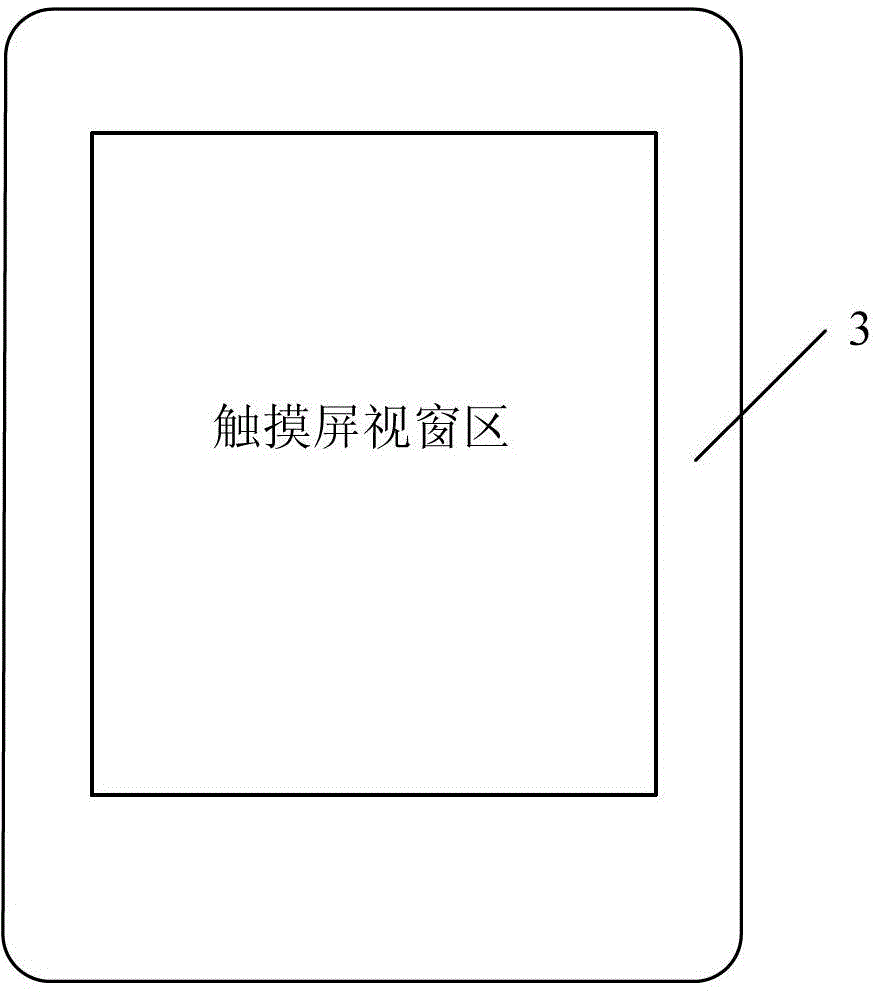
[0004] Since the outlet area without touch function needs to be included outside the graphic area with touch function, in the existing design, such as image 3 and Figure 4 As shown, it is necessary to reserve a certain frame area outside the touch screen area of ​​the fuselage for outgoing wires, which leads to the problem that the frame of the current capacitive touch screen is relatively wide
Under the trend of thinning the terminal and maximizing the display area of ​​the touch screen, compressing the width is particularly important. However, in the current technical solution, since the outgoing line area cannot be touched by the touch screen, no matter how compressed the width of the outgoing line area, the frame cannot be completely eliminated. The existence of , goes against the general trend of compressing the terminal width

Method used


Image

  • Capacitive touch screen and terminal
  • Capacitive touch screen and terminal
  • Capacitive touch screen and terminal

Examples


Embodiment 1

[0024] Embodiment 1 of the present invention provides a capacitive touch screen, Figure 5 This is an implementation manner of the technical solution provided by Embodiment 1 of the present invention. See Figure 5 to Figure 7 The capacitive touch screen includes a substrate 6, and the substrate includes a first surface and a second surface. The touch screen also includes:

[0025] The first pattern 8 and the first exit line 81 formed on the first surface of the substrate, the first pattern covering a part of the first surface of the substrate, and the first exit line is along the edge of the first pattern The exit line in the first direction, the first exit line is formed in the remaining area of ​​the first surface of the substrate except for the first pattern.

[0026] The second pattern 9 and the second exit line 91 formed on the second surface of the substrate, the second pattern covering a part of the second surface of the substrate, and the second exit line is along the se...

Embodiment 2

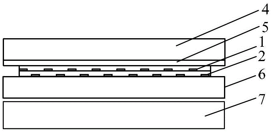
[0031] Embodiment 2 of the present invention provides a capacitive touch screen, which is a specific implementation of the technical solution provided in Embodiment 1. Figure 5 It is a schematic cross-sectional view of a capacitive touch screen provided by Embodiment 2 of the present invention. The capacitive touch screen includes a substrate 6, and a cover 4 is provided on the outside of the touch screen substrate. The 7 is a display. The display can be a liquid crystal display LCD or a light emitting diode display (Light Emitting Diode, LED) or other types The display is not limited in the embodiment of the present invention.

[0032] Embodiment 2 of the present invention mainly describes the touch screen provided by the embodiment, such as Figure 5 As shown, the first surface of the substrate 6 is the upper surface of the substrate, and the second surface of the substrate 6 is the lower surface of the substrate. Preferably, the first pattern extends from the first side of th...

Embodiment 3

[0040] Embodiment 3 of the present invention provides a terminal device using the touch screen as described in the foregoing embodiment, that is, an embodiment of the present invention also provides a terminal. The terminal includes a touch screen, the touch screen includes a substrate, and the substrate includes a first Surface and second surface, the touch screen further includes: a first pattern and a first outlet line formed on the first surface of the substrate, the first pattern covering a partial area of ​​the first surface of the substrate, the The first outlet line is the outlet line of the first pattern along the first direction, and the first outlet line is formed on the remaining area of ​​the first surface of the substrate except for the first pattern; formed on the second surface of the substrate The second pattern covers a part of the second surface of the substrate and the second outlet line, the second outlet line is the outlet line of the second pattern along t...


PUM


Abstract

Embodiments of the present invention disclose a capacitive touchscreen and a terminal, which can reduce or even eliminate a width of a terminal border. The capacitive touchscreen includes: a substrate including a first surface and a second surface; a first pattern and a first outgoing wire that are formed on the first surface of the substrate, where the first pattern covers a partial area of the first surface of the substrate, and the first outgoing wire is formed in a remaining area, except the first pattern, of the first surface of the substrate; and a second pattern and a second outgoing wire that are formed on the second surface of the substrate, where the second pattern covers a partial area of the second surface of the substrate, and the second outgoing wire is formed in a remaining area, except the second pattern, of the second surface of the substrate. The first surface and the second surface are two opposite surfaces of the substrate. A perpendicular projection, on the first surface, of the second pattern covers at least the remaining area, except the first pattern, on the first surface.

Description

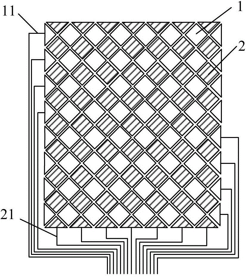
Technical field [0001] The invention relates to the field of terminals, in particular to a capacitive touch screen and a terminal. Background technique [0002] With the development of technology, the application of capacitive touch screen technology has occupied a dominant position in smart portable devices. Such as figure 1 As shown, the capacitive sensor device of the touch screen above the liquid crystal display 7 (LCD, Liquid Crystal Display) is coated with a layer of transparent conductive material, such as indium tin oxide (ITO, Indium Tin Oxide) material, on the substrate 6, According to the requirements of the touch integrated circuit (IC, Integrated Circuit,), the corresponding conductive pattern is etched, and the ITO material is usually used, that is, the ITO pattern. In the prior art, each conductive pattern usually includes a horizontal slider and a vertical slider. The horizontal slider is the horizontal electrode (X electrode), which is transparent ITO in the hor...

Claims


Application Information

Patent Timeline
Patent Type & Authority Patents(China)
IPC IPC(8): G06F3/044
CPCG06F2203/04103G06F1/1643G06F3/0416G06F3/044G06F3/0412G06F3/04166G06F3/0445G06F3/0446
Inventor 王鹏
Owner HONOR DEVICE CO LTD
Learn More