Pressure relief structure
A technology of pressure relief structure and pressure relief hole, which is applied in cooking utensils, household utensils, applications, etc., can solve problems such as danger and poor thermal insulation performance, and achieve the effect of protecting the safety of use
- Summary
- Abstract
- Description
- Claims
- Application Information
AI Technical Summary
Problems solved by technology
Method used
Image

Examples
Embodiment 1
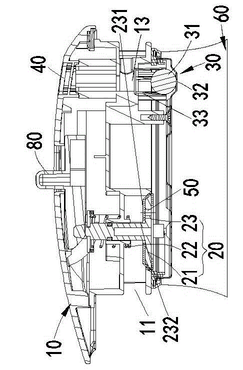
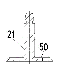
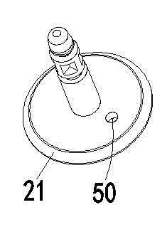
[0027] Such as Figure 1-3 As shown, a pressure relief structure includes a pot cover structure 10 and a cavity 60, the pot cover structure 10 is provided with a water outlet 11, the pot cover structure 10 is buckled above the cavity 60, and the pot cover structure 10 is provided with a The water outlet valve structure 20 that opens and closes the connection channel between the water outlet 11 and the cavity 60. The first pressure relief hole 50 for discharging steam is provided in the lid structure 10. The first pressure relief hole 50 is provided with elastic Cover sheet, when the elastic cover sheet is lifted by the high-pressure steam in the cavity 60, a gap is formed between the first pressure relief hole 50 and the elastic cover sheet, and the gap can communicate with the cavity 60 When the air pressure in the cavity 60 is too low to lift the elastic covering sheet, the first pressure relief hole 50 is covered, and the cavity 60 cannot communicate with the external a...
Embodiment 2
[0035] Such as Figure 4 As shown, the lid structure 10 is provided with a plane 12, the upper surface of the plane 12 communicates with the outside atmosphere through the connection gap between the lid structure 10 and the water outlet valve structure 20, and the first pressure relief hole 50 is set On the plane 12, the plane 12 is a boss structure, the inlet port of the first pressure relief hole 50 communicates with the cavity 60, and the air outlet port of the first pressure relief hole 50 passes through the passage of the second sealing ring. The hole 71 communicates with the outside atmosphere through the connection gap between the pot cover structure 10 and the water outlet valve structure 20; the second sealing ring 70 is sleeved on the plane 12, and the upper annular plane 72 of the second sealing ring Cover the first pressure relief hole 50 . Other undescribed parts are the same as the first embodiment.
[0036] The working principle of this embodiment is: the firs...
Embodiment 3
[0038] Such as Figure 5 , 6 As shown, the elastic covering sheet is provided with a clamping portion 91 and a covering portion 92, the lid structure 10 is provided with a plane 12, the first pressure relief hole 50 is provided on the plane 12, and the first pressure relief hole 50 is provided on the plane 12. Next to the press hole 50, a snap hole 14 is provided corresponding to the clip part 91, and the clip part 91 passes through the clip hole 14 to clip and fix with the clip hole 14, and the cover part 92 covers the first pressure relief hole 50, and other parts not described are the same as the second embodiment.
[0039] The working principle of this embodiment is: when the steam pressure in the cavity 60 pushes up the covering portion 92 of the elastic covering sheet, a gap is formed between the covering portion 92 of the elastic covering sheet and the first pressure relief hole 50, and the cavity 60 The steam is directly discharged from the gap, and finally directed ...
PUM
 Abstract
Description
Claims
Application Information
 - R&D
- Intellectual Property
- Life Sciences
- Materials
- Tech Scout
- Unparalleled Data Quality
- Higher Quality Content
- 60% Fewer Hallucinations
Browse by: Latest US Patents, China's latest patents, Technical Efficacy Thesaurus, Application Domain, Technology Topic, Popular Technical Reports.
© 2025 PatSnap. All rights reserved.Legal|Privacy policy|Modern Slavery Act Transparency Statement|Sitemap|About US| Contact US: help@patsnap.com