
Cold stamping process method for oil tank bracket of heavy vehicle

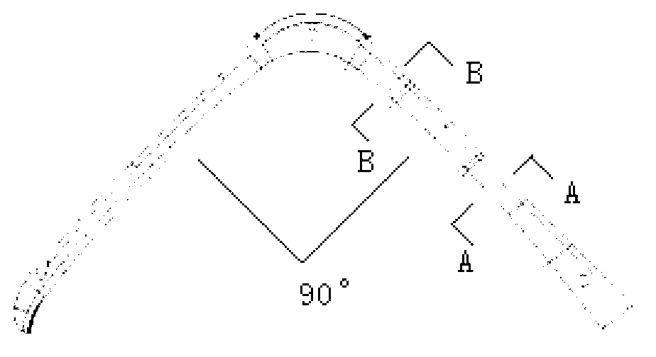
A process method, cold stamping technology, applied in the field of cold stamping process, to achieve the effect of eliminating thinning and out-of-tolerance, solving partial cracking, and improving the qualified rate of finished products

Active Publication Date: 2012-10-10
重汽(济南)传动轴有限公司
View PDF5 Cites 1 Cited by
  • Summary
  • Abstract
  • Description
  • Claims
  • Application Information

AI Technical Summary

Problems solved by technology

[0007] The outstanding defect of the original process is in Figure 4 Where shown, there is cracking or thinning out of tolerance

Method used


Image

  • Cold stamping process method for oil tank bracket of heavy vehicle
  • Cold stamping process method for oil tank bracket of heavy vehicle
  • Cold stamping process method for oil tank bracket of heavy vehicle

Examples


Embodiment Construction

[0027] The present invention will be further described below in conjunction with the accompanying drawings and embodiments.

[0028] Such as Figure 8 As shown, the cold stamping process of the heavy-duty vehicle fuel tank bracket, the steps are as follows:

[0029] 1) Blanking; 2) Preforming 4; 3) Shaping 5; 4) Punching; 5) Punching.

[0030] Step 1) Blanking: drop out the shape of the blank.

[0031] The preforming 4 in step 2) is: change the angle between the two arms from 120° to 130° on the blank to form a workpiece, and at the same time Shaped sections are formed in one step and pressed into place.

[0032] Reshaping 5 in step 3) is to perform angle shaping on the arc and straight line transition area of ​​the workpiece, so that the angle between the two arms reaches the final 90° state of the product.

[0033] To determine the angle range of the angle between the two arms during preforming 4, it should be considered that no defects will occur in the subsequent shap...


PUM


Abstract

The invention discloses a cold stamping process method for an oil tank bracket of a heavy vehicle. The cold stamping process method comprises the following steps of: 1) blanking; 2) preforming; 3) forming; 4) punching; and 5) punching, wherein the blanking in the step 1) comprises: forming the appearance of a blank; the preforming in the step 2) comprises: changing an included angle between two arms of the blank between 120 and 130 degrees to form a part, and performing one-step molding on the section of the part and pressing in place; and the forming in the step 3) comprises: performing angle forming on arc and linear transition areas of the part, so that the included angle between the two arms is finally in a 90-degree state of the product. The phenomenon that a part of the part is cracked in the punching process is avoided, and the yield of the finished product is greatly improved; and meanwhile, according to the test, the thinning over-proof potential hidden danger is completely eliminated.

Description

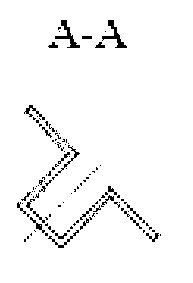
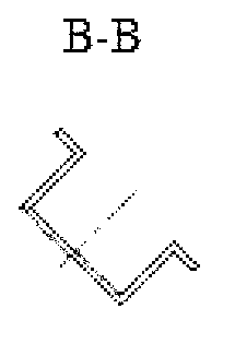
technical field [0001] The invention relates to a cold stamping process method of a heavy-duty vehicle fuel tank bracket. Background technique [0002] The shape of the fuel tank bracket for heavy-duty vehicles is an overall L-beam type, which is one of the more complicated beam-type parts of thick plates. It uses high-strength steel plates, and the cross-section The deformation section is not equal and the forming depth is large, and the forming depth in the middle arc area is the largest; the two ends are formed by large arcs; the angle between the two straight arms is 90° (such as Figure 1-Figure 3 shown). [0003] In addition to the radial tensile stress in the arc region and its own bending tensile stress in the forming of the bracket, the key is the additional tensile stress generated along the straight arm to both ends, which has reached a large value, which affects the forming stability of the workpiece . [0004] Due to the unique forming depth, variable cross s...

Claims


Application Information

Patent Timeline
Patent Type & Authority Applications(China)
IPC IPC(8): B21D35/00
Inventor 肖洪陵吴蓉李忠敬
Owner 重汽(济南)传动轴有限公司
Learn More