
Oil blockage cover on oil pan, and oil pan

A technology of oil pan and port cover, which is applied in the direction of engine components, machine/engine, engine lubrication, etc., and can solve problems such as oil leakage accidents, poor anti-loosening effect, and uneven tightening degree

Active Publication Date: 2014-09-03
GREAT WALL MOTOR CO LTD
View PDF6 Cites 0 Cited by
  • Summary
  • Abstract
  • Description
  • Claims
  • Application Information

AI Technical Summary

Problems solved by technology

[0002] With the improvement of manufacturing technology, the oil pan used in automobiles has changed from aluminum to plastic. Due to the change of material, the oil pan oil plug cap originally installed on the oil drain hole of the oil pan is tightened. Different, the anti-loosening effect is not good, and it may be separated when subjected to vibration and impact, resulting in oil leakage accidents

Method used


Image

  • Oil blockage cover on oil pan, and oil pan
  • Oil blockage cover on oil pan, and oil pan
  • Oil blockage cover on oil pan, and oil pan

Examples


Embodiment 1

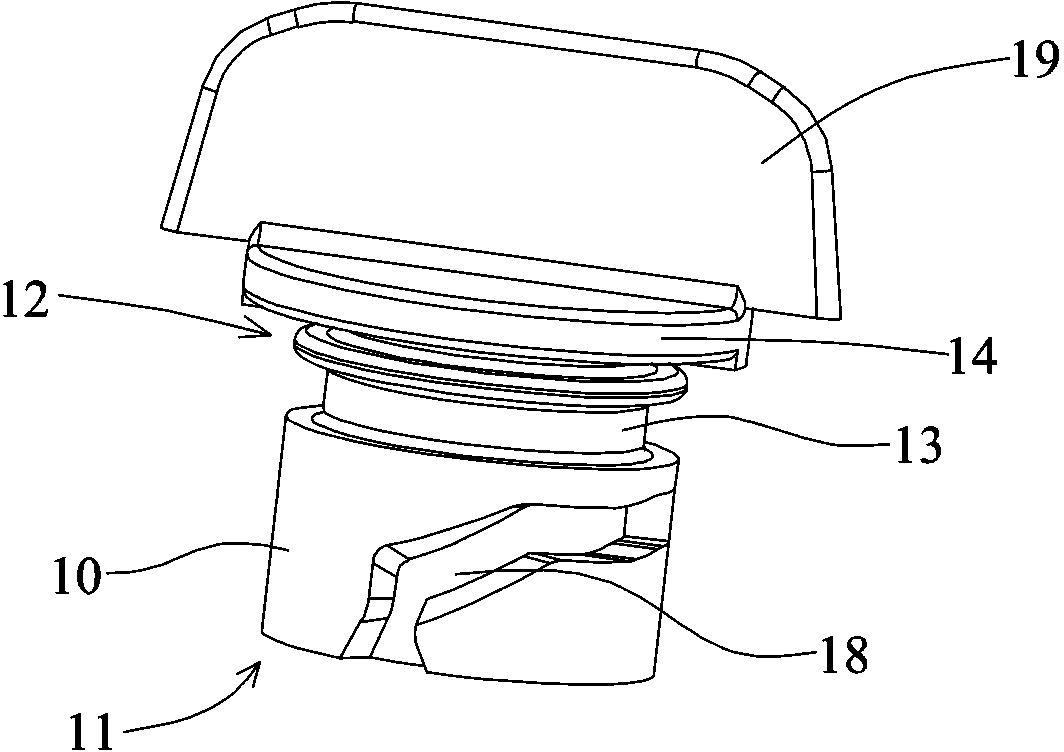
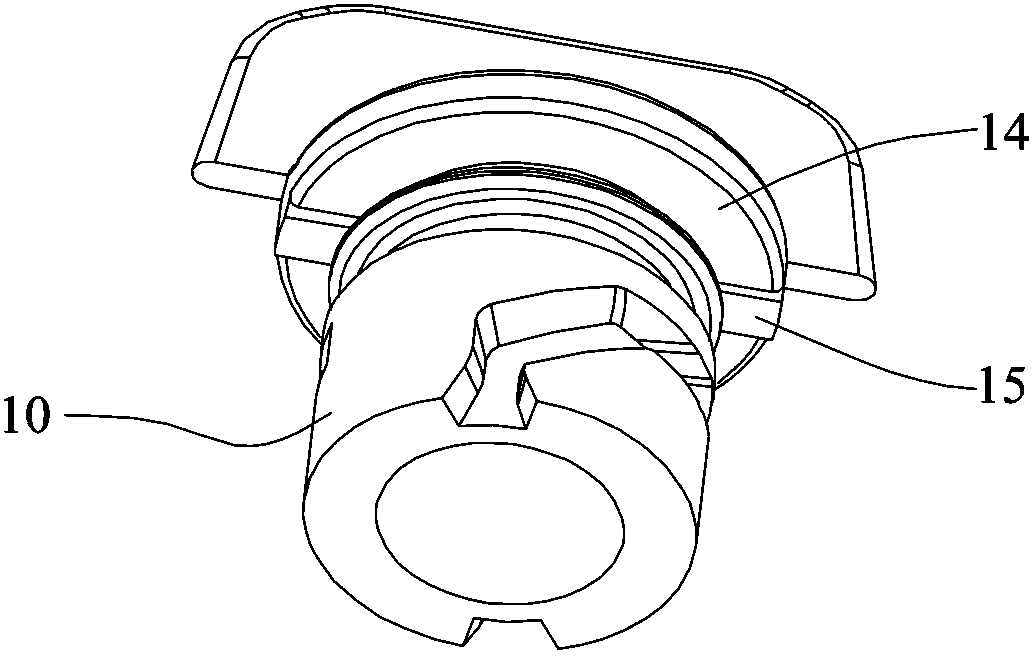
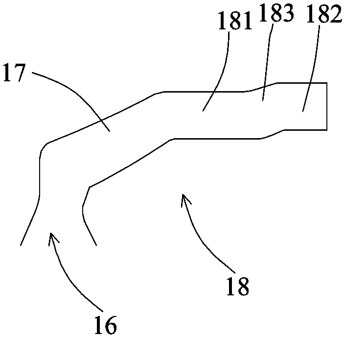
[0026] Such as Figure 1 to Figure 3 As shown, the oil pan oil plug cap of the present invention includes a columnar plastic body 10, one end of the body 10 is an insertion end 11, and the end opposite to the insertion end 11 is a cut-off end 12, which is fixed at the cut-off end 12. Connecting a boss 14, the end surface of the boss 14 connected with the body 10 is provided with a protruding clamping column 15, and a knob 19 is fixedly connected to the boss 14, and the side of the knob 19 protrudes from the boss 14 of the outer wall. An annular groove 13 is provided between the insertion end 11 and the cut-off end 12, and the annular groove 13 is used for inserting a sealing ring to play a role of sealing. The main body 10 is also provided with guide grooves 18 , and the said guide grooves 18 are provided as two or more than one arranged along the circumference of the axis of the main body 10 .

[0027] The guide groove 18 includes a section of guide groove 16 starting from ...

Embodiment 2

[0030] Such as Figure 4 and Figure 5 As shown, the embodiment of the present invention is an adaptive installation structure for the oil plug cover of the oil pan in the first embodiment, that is, an oil pan is disclosed, which includes a plastic shell 20, An oil drain hole 21 is provided on the casing 20 , and the oil drain hole 21 can be inserted into the body 10 . A guide column 22 corresponding to the guide groove 18 is provided in the drain hole 21, the width of the guide column 22 is not greater than the width of the guide groove 16 and the first transverse region 181 and the second transverse region 182, and can be freely positioned in the guide groove. 16 and slide in the first transverse zone 181 and the second transverse zone 182. On the outer end surface 26 of the oil drain hole 21 is provided a locking groove 23 , and the outer end surface 26 is provided with a slope 25 transitioning to the bottom of the locking groove 23 . The clamping slot 23 cooperates with...


PUM


Abstract

The invention relates to an oil pan and an oil plug cap used on the oil pan. The oil pan oil plug cover consists of a columnar plastic body with two ends respectively being the insertion end and the cut-off end. The surface of the body is also provided with a guide groove including a guide groove and a first transverse area, and a protrusion is fixedly connected to the cut-off end. The platform has a protruding clamping post on the end face of the boss connected to the body. The oil sump includes a plastic shell provided with an oil drain hole, the inner wall of the oil drain hole has a guide column suitable for being inserted into the guide groove and the first transverse area, and the outer end surface of the oil drain hole has a guide column for When the clamping post slides into the slot, the guide post can be located in the first transverse area of ​​the guide slot. The guide column of the oil pan enters the first transverse area of ​​the guide groove on the oil pan cover, and the clamping column enters the slot, so that the oil cover of the oil pan can be installed accurately and the connection degree is ensured. Consistency ensures the anti-loosening effect.

Description

technical field [0001] The invention relates to a sealing cover, in particular to an oil pan oil plugging cover used on an oil pan, and also relates to an oil pan installed with the oil pan oil plugging cover. Background technique [0002] With the improvement of manufacturing technology, the oil pan used in automobiles has changed from aluminum to plastic. Due to the change of material, the oil pan oil plug cap originally installed on the oil drain hole of the oil pan is tightened. Not one, the anti-loosening effect is not good, and the phenomenon of detachment may occur when subjected to vibration and impact, resulting in oil leakage accidents. Contents of the invention [0003] In order to solve the deficiencies in the prior art, the present invention provides an oil plug cover and an oil pan, which effectively ensure the consistency of the connection degree between the two, and have a better anti-loosening effect. [0004] In order to achieve the above object, the oil...

Claims


Application Information

Patent Timeline
Patent Type & Authority Patents(China)
IPC IPC(8): F01M11/00
Inventor 吴文能吴兆平郑焕成刘艳
Owner GREAT WALL MOTOR CO LTD
Learn More