Electronic illuminating apparatus for simulating real fire
A lighting device and a technology for simulating real fire, which is applied to lighting devices, components of lighting devices, lamp circuit layout, etc., can solve the problems of unrealistic and large differences in visual experience, and achieve visual effects that are realistic and visually enhanced. The effect of experience
- Summary
- Abstract
- Description
- Claims
- Application Information
AI Technical Summary
Problems solved by technology
Method used
Image
Examples
Embodiment 1
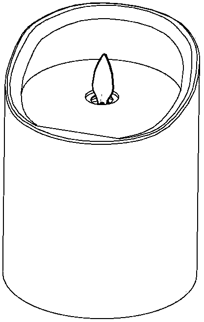
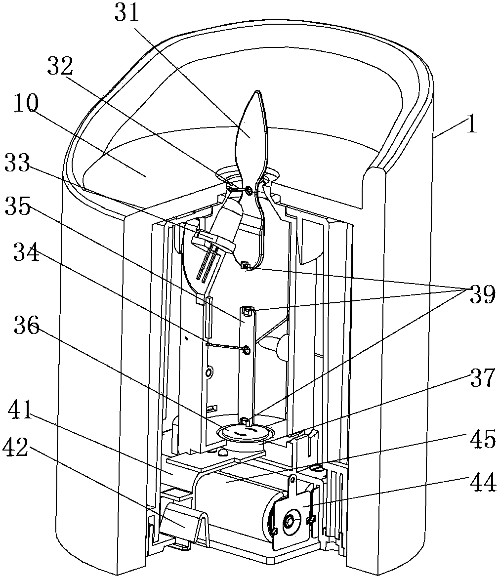
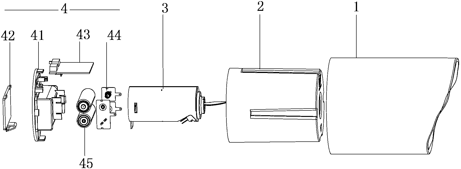
[0033] The specific product of this embodiment is an electronic candle, please combine figure 1 , figure 2 , image 3 , Figure 4 with Figure 5 As shown, figure 1 This is the schematic diagram of the appearance of the electronic candle in this example, which simulates the shape of the candle as a whole, including: a shell 1; a shell 2 set in the shell 1; a movement 3 and a base 4 are installed in the shell 2. A shell through hole is opened in the middle of the top of the shell 2 in which a flame piece is arranged. The shape of the flame piece extending out of the shell through hole is simulated as the wax flame when a candle is lit, and the light emitted by the light emitting element on the movement Projected at a certain angle on the part of the flame piece protruding from the through hole, and the flame piece can sway freely under the action of natural wind or the swing mechanism provided in the movement, so that it looks like a certain distance The real candle flame is sway...
Embodiment 2
[0047] Please refer to Figure 8 As shown, in this example, the oscillating mechanism of the first embodiment is subtracted to cancel the interlocking piece 35 part in the middle. The coil 37 is close to the lower end of the flame piece 31, and the magnet polarity at the lower end of the flame piece 31 is generated by the coil 37. The different magnetic fields cause the two to repel each other, and the flame piece 31 can also keep shaking.
Embodiment 3
[0049] In this example, for the swing mechanism of the movement 3 in the first embodiment, the structure of this example is adopted, please refer to Picture 9 As shown, it includes a lanyard 301, a swing block 302, a rotating block 303, a motor fixing block 304, and a motor 305; the upper end of the lanyard 301 is hung on the lower end of the flame plate 31, the lower end of the lanyard 301 is connected to the swing block 302, and the motor 305 is The motor fixing block 304 is fixed in the casing of the movement, and the rotating block 303 is fixedly connected to the output shaft of the motor 305; in the natural state (only under the action of its own gravity and not under external force), the swing block 302 hangs by its own weight On the lanyard 301, the lower end of the swinging block 302 contacts the rotating block 303; when the motor 305 is driven, the rotating block 303 will continuously collide with the swinging block 302, and the continuous shaking of the swinging block ...
PUM
 Abstract
Description
Claims
Application Information
 - R&D
- Intellectual Property
- Life Sciences
- Materials
- Tech Scout
- Unparalleled Data Quality
- Higher Quality Content
- 60% Fewer Hallucinations
Browse by: Latest US Patents, China's latest patents, Technical Efficacy Thesaurus, Application Domain, Technology Topic, Popular Technical Reports.
© 2025 PatSnap. All rights reserved.Legal|Privacy policy|Modern Slavery Act Transparency Statement|Sitemap|About US| Contact US: help@patsnap.com


