Electric hammer

A technology of electric hammers and transmission parts, applied in nailing tools, manufacturing tools, etc., can solve problems such as uncompact structure, motor stall, crank slider mechanism can not achieve hitting, etc., to achieve the effect of compact structure and small size

Inactive Publication Date: 2015-04-08
NANJING CHERVON IND
View PDF15 Cites 0 Cited by
  • Summary
  • Abstract
  • Description
  • Claims
  • Application Information

AI Technical Summary

Problems solved by technology

The problem with this type of electric hammer is that the crank slider mechanism cannot achieve real hitting, and is essentially a "push" nail mechanism. Under the same motor power, the efficiency of pushing nails is much lower than that of driving nails. The second is that during each nail pushing process, the crank slider mechanism must push the nail pushing element to travel the same stroke. When the nail encounters a hard object and the resistance is too large, it is easy to cause the motor to stall and cause the motor to be damaged; The third is that the motor is placed on the front or rear side of the handle, and it is connected with the transmission mechanism to occupy a large space, which makes the electric hammer larger and not convenient to carry and operate.
Although the electric hammer utilizes spring energy storage to realize instant hitting on the nail, it can only be clicked one by one, and cannot be hit continuously, and the hitting force generated only by the energy released by the spring is not efficient, resulting in the electric hammer being ineffective. It is suitable for frequent use as a conventional tool; in addition, its motor is located in the casing under the gun head, completely separated from the handle, and there is still the problem of not being compact

Method used


Image

  • Electric hammer
  • Electric hammer
  • Electric hammer

Examples


Embodiment Construction

[0015] The specific implementation manners of the present invention will be further described in detail below in conjunction with the accompanying drawings.

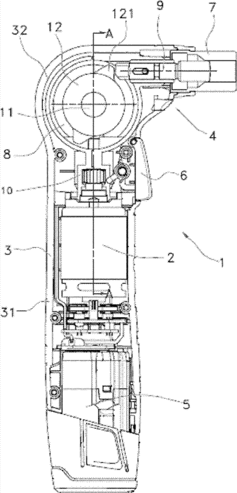
[0016] Such as figure 1 As shown, it is a schematic diagram of the electric hammer 1 of the present invention. The electric hammer 1 includes a casing 3, and the casing 3 is formed by combining two halves of the shell, and its main part forms a grip handle 31 in the longitudinal direction. The switch 6 for controlling the start and stop of the motor in the casing 3 is installed on the 31 position, the DC battery pack 5 is installed on the lower end of the casing 3, and the upper end head 32 of the casing 3 has a gun nozzle part 4, and the gun nozzle part 4 accommodates a nailing device 7 for driving fasteners such as nails.

[0017] In this embodiment, the battery pack 5 and the grip handle 31 are arranged substantially coaxially, the outer surfaces of the shell of the battery pack 5 and the casing 3 are adjacent to eac...


PUM


Abstract

The invention provides an electric hammer, which includes: an enclosure, which supports a nail striking device; a motor placed inside the enclosure, a motor-driven transmission mechanism and an impact assembly. The impact assembly contains an impact wheel and an intermediate shaft supporting the impact wheel, the impact portion of which impacts the stricken shaft of the nail striking device. The intermediate shaft is rotatably supported on a first supporting member and a second supporting member, which are respectively located on two sides of the impact assembly. The transmission mechanism includes a first transmission member and a second transmission member, with the first transmission member in driving connection with the intermediate shaft, wherein the axis of the first transmission member is parallel to the axis of the second transmission member. The electric hammer of the invention has a compact structure and small size, and especially the distances between center of the striking shaft and the two sides of the head of the enclosure are shorter, so that striking operation on a nail in a narrow spatial position, such as a corner, is more likely to realize functionally.

Description

technical field [0001] The invention relates to an electric tool, in particular to an electric hammer capable of striking fasteners such as nails. Background technique [0002] Electric hammers are a commonly used hand-held tool with a wide variety. According to the power source, electric hammers can be divided into two categories: pneumatic and electric. Among them, the pneumatic electric hammer must be equipped with a compressed air source, so its use is limited. The basic structure of the electric hammer can be summarized as follows: the motor placed in the gun body is connected with the nail rod placed at the gun head through the rotation-linear transmission mechanism, so that the electrical energy can be converted into reciprocating mechanical energy under the control of the switch. [0003] US Patent No. US6431430 and PCT International Patent Application Publication No. WO2006 / 008546 both disclose an electric hammer with a crank slider mechanism as a rotation-linear...

Claims


Application Information

Patent Timeline
Patent Type & Authority Patents(China)
IPC IPC(8): B25C1/06
Inventor 魏淦
Owner NANJING CHERVON IND
Why Eureka
Try Eureka