Columnar reinforced gabion retaining wall and construction method thereof

A retaining wall and column technology, applied in artificial islands, water conservancy projects, infrastructure projects, etc., can solve the problems of high material consumption, unfavorable later maintenance, unfavorable on-site construction, etc., and achieve simple construction technology, simple repeated operations, The effect of saving labor

Active Publication Date: 2014-08-13
HUNAN PROVINCIAL COMM PLANNING SURVEY & DESIGN INST CO LTD
View PDF7 Cites 0 Cited by
  • Summary
  • Abstract
  • Description
  • Claims
  • Application Information

AI Technical Summary

Problems solved by technology

This structure has the following defects: firstly, the retaining wall surface is not beautiful due to the existence of beams; secondly, when the flat layer reinforced structure is high, lifting equipment is required to install prefabricated components, otherwise components need to be poured on site
[0004] Due to the large size of the traditional reinforced gabion structure, it is not conducive to on-site construction. In addition, because the end of the traditional reinforced gabion structure adopts an integral gabion unit, or a baffle is added to separate it, the material consumption is large , the construction requirements are high, and the integral gabion unit also acts as a wall net, which causes large wear and tear, which is not conducive to later maintenance

Method used


Image

  • Columnar reinforced gabion retaining wall and construction method thereof
  • Columnar reinforced gabion retaining wall and construction method thereof
  • Columnar reinforced gabion retaining wall and construction method thereof

Examples


Embodiment 1

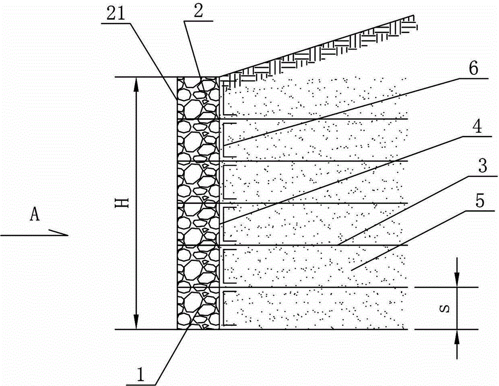
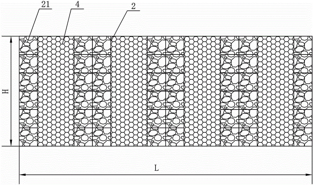
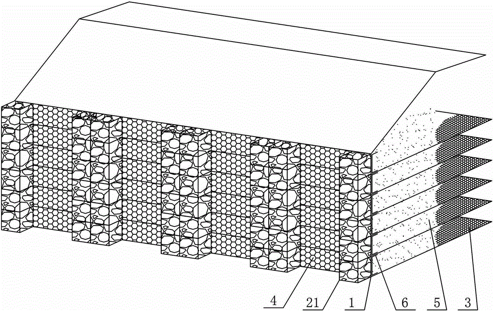
[0033] a kind of like Figure 1 to Figure 3 The vertical column type reinforced gabion retaining wall of the present invention is shown. The retaining wall has a length L of 10m and a height H of 6m.

[0034] The upright column-type reinforced gabion retaining wall in this embodiment is mainly composed of four sub-walls (the length of each side sub-wall in the horizontal direction is 2.5m) arranged closely to each other along the horizontal direction, and each side sub-wall It is mainly composed of 6 reinforced gabion units 1 (the height s of each reinforced gabion unit 1 is 1m) stacked in sequence from bottom to top. The reinforced gabion unit 1 includes gabion components 2 and is connected The tailing type ribbed net 3, the top of the ribbed net 3 is compacted with a structural fill 5 (the structural fill 5 is a mixture of gravel, coarse sand, and clay, and the bulk density of the structural fill 5 in this embodiment is 1.85 t / m 3 , the friction angle is 30°), the gabion a...

Embodiment 2

[0045] a kind of like Figure 8 to Figure 10 The shown ladder-column reinforced gabion retaining wall of the present invention has roughly the same structure and manufacturing method as in Example 1, the difference being that in Example 2, when the wall is divided into parts for construction, in order to reduce the lateral earth pressure, Each reinforced gabion unit 1 is stacked in steps along the vertical direction, that is, the gabion column formed by the stacking of gabion cages 21 has a slope. For the specific stacking method, refer to Figure 8 and Figure 9 , and finally get as Figure 8 , Figure 10 The ladder-column reinforced gabion retaining wall is shown, in which the gabion column maintains a slope of 1:0.3. The length L of the stepped column type reinforced gabion retaining wall of the present embodiment is 10m, and the height H is 10m. s is 1m) are formed by superimposing successively from bottom to top. In practice, the slope of the gabion cage 21 can also ...


PUM


Abstract

The invention discloses a column-type reinforced gabion retaining wall. The retaining wall includes more than one sub-wall body. The unit includes a gabion component and a trailing ribbed net connected with the gabion component. Backfill soil is compacted above the ribbed net. The gabion component includes at least two spaced apart gabion cages, and the spaced apart gabion net The cage is connected as a whole by the vertical wall network located on its side. The gabion cage is filled with stone materials, and the gabion cages in the two adjacent reinforced gabion units are superimposed to form the gabion cages distributed at intervals. column. The invention also discloses a construction method of the column-type reinforced gabion retaining wall, which includes the steps of material preparation, forming of the reinforced gabion unit, forming of the sub-wall body, integral forming of the column-type reinforced gabion retaining wall, and the like. The invention has the advantages of surface greening, convenient construction, low cost, wide application range, good mechanical properties and the like.

Description

technical field [0001] The invention relates to a retaining wall and a construction method thereof, in particular to a retaining wall provided with a gabion structure and a construction method thereof. Background technique [0002] Existing building retaining structures include flat-floor reinforced structures, reinforced gabion structures, and the like. [0003] The traditional flat-story reinforced structure is a soil retaining structure composed of beams, baffles, ribs and filling soil. Its mechanical characteristics are that the lateral pressure of the soil is transmitted to the beams through the baffles, and then transmitted from the beams to the ribs. Then the balance is maintained by the pull-out force of the ribs. This structure has the following defects: firstly, the retaining wall surface is not beautiful due to the existence of beams; secondly, when the flat layer reinforced structure is high, lifting equipment is required to install prefabricated components, oth...

Claims


Application Information

Patent Timeline
Patent Type & Authority Patents(China)
IPC IPC(8): E02D29/02
Inventor 彭立黄向京杜勇立王祥王珏
Owner HUNAN PROVINCIAL COMM PLANNING SURVEY & DESIGN INST CO LTD
Why Eureka
Try Eureka