Solar simulator and measurement method using same

The technology of a solar simulator and measurement method is applied in the field of solar simulators to achieve the effects of prolonging lamp life, shortening measurement time, and shortening luminous time

Inactive Publication Date: 2012-10-17
NISSHINBO MECHATRONICS
View PDF4 Cites 3 Cited by
  • Summary
  • Abstract
  • Description
  • Claims
  • Application Information

AI Technical Summary

Problems solved by technology

Therefore, only one set of data (illuminance, solar cell output current and voltage) can be collected during one flash lighting.

Method used


Image

  • Solar simulator and measurement method using same
  • Solar simulator and measurement method using same
  • Solar simulator and measurement method using same

Examples


Embodiment 1

[0082] according to Figure 5 An example of a solar cell in the vicinity of a current / voltage value (optimum operating point) showing maximum power ( Figure 9 The area M) responds slowly, while in other load areas ( Figure 9 The area N1 and area N2) respond quickly. In this embodiment, the electronic load command is controlled by current. The operating current of the solar cell is manipulated according to the electronic load command, and the voltage value output from the solar cell as the object to be measured is measured. Figure 5 (b) represents the patterns a, b, and c in which the current command changes with time. Figure 5 (a) is the output characteristic curve obtained according to the modes a, b, and c of the current command changing with time.

[0083] exist Figure 5 In (a) and (b), pattern a (dotted line) represents a conventional measurement method of measuring a solar cell with a current command at a constant speed. Pattern b (single-dashed line) represent...

Embodiment 2

[0090] according to Figure 7 Next, an example of a solar cell in another mode will be described. The solar cell is in the vicinity of the current / voltage value (optimum operating point) showing the maximum power ( Figure 9 The area M) responds slowly, while in other load areas ( Figure 9 Region N1 and region N2) solar cells with fast response. In this embodiment, the electronic load command is controlled by voltage. The operating voltage of the solar cell is controlled according to the electronic load command, and the current value output from the solar cell as the object to be measured is measured. Figure 7 (b) represents the patterns a, b, and c of the voltage command changing with time. Figure 7 (a) is the output characteristic curve obtained according to the modes a, b, and c of the voltage command changing with time.

[0091] exist Figure 7 In (a) and (b), pattern a (dotted line) represents a conventional measurement method of measuring a solar cell with a volt...

Embodiment 3

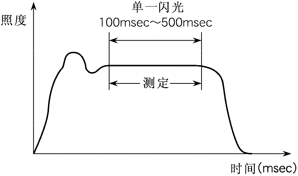
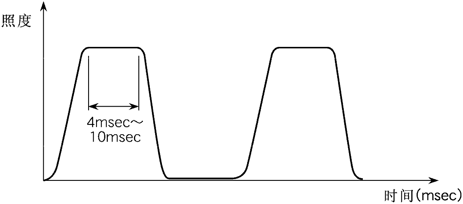
[0098] When using a light source with a short light emitting time, such as Figure 8 As shown, multiple flashes can be made to perform split measurement. For example, in the case of changing the current with time according to the single-dot chain line b of the conventional measurement method in Example 1, when measuring the output characteristics of a solar cell with a relatively slow response characteristic, the pulse waveform can be divided into and Figure 8 Measurement points corresponding to parts A and B of the pulse waveform in (a). exist Figure 8 (b) at the first luminous place, according to the assay method of the present invention Figure 8 (a) The measurement point of part A is measured. exist Figure 8 (b) at the second luminous place, according to the assay method of the present invention Figure 8 (a) The measurement point of part B is measured. and Figure 5 (b) and Figure 7 As in mode c of (b), after the load command speed is properly adjusted by the me...


PUM


Abstract

Disclosed is a measurement method using a solar simulator which can shorten the light emission duration of a light source lamp and measure the output characteristics of a solar cell, even when said solar cell has slow response characteristics. Further disclosed is a solar simulator for implementing the measurement method. A measurement method using a solar simulator has: a step whereby one or more light sources are made to simultaneously emit a flash in which the top of the pulse waveform becomes level; and a step whereby a multi-point measurement of the current and voltage output from a solar cell to be measured is carried out by irradiating the flash onto the solar cell and sweeping the electronic load of the solar cell, while using an illuminance detector for illuminance control. The speed of instructions to an electronic load command is variably controlled in accordance with the response characteristics of the solar cell to be measured, and the current and voltage output from the solar cell are measured while the flash is irradiated onto the solar cell to be measured.

Description

technical field [0001] The present invention relates to a solar simulator for measuring the current-voltage characteristics (hereinafter simply referred to as characteristics) of photoelectric conversion elements such as solar cells and their panels with high speed and high accuracy, and the measurement using the solar simulator method. Background technique [0002] The photoelectric conversion characteristics of photoelectric conversion elements such as solar cells, photoexcited electric devices, and photosensors are measured by measuring the current-voltage characteristics of the photoelectric conversion elements under light irradiation. In the characteristic measurement of the solar cell, the voltage is taken as the horizontal axis and the current is taken as the vertical axis, and the collected data are plotted to obtain the output characteristic curve. This curve is generally referred to as an IV curve. [0003] As the measurement method described above, a method usin...

Claims


Application Information

Patent Timeline
Patent Type & Authority Applications(China)
IPC IPC(8): H01L31/04
CPCG01J1/08G01R31/2605H02S50/10Y02E10/50
Inventor 下斗米光博筱原善裕
Owner NISSHINBO MECHATRONICS
Why Eureka
Try Eureka