Supercharge Your Innovation With Domain-Expert AI Agents!

Centrifugal pump formed in double-suction volute chamber

A centrifugal pump and volute chamber technology, which is applied in the field of double-suction volute centrifugal pumps, can solve the problems of easily generating radial force and radial force cannot be eliminated, so as to eliminate radial force, improve efficiency, and reduce pump body Vibration and noise effects

Inactive Publication Date: 2012-10-24
周游
View PDF0 Cites 0 Cited by
  • Summary
  • Abstract
  • Description
  • Claims
  • Application Information

AI Technical Summary

Benefits of technology

This technology helps reduce stress on equipment by eliminating any negative impacts caused from external forces or improving its performance over time without adding extra weight or making it more expensive than usual for regular use.

Problems solved by technology

The technical problem addressed by this patented design for Single Stage Double Sucking Voluage Pumps (SSV) used in Chinese Patents: The current designs have poor efficiency when they are optimized towards their best possible range due to excessive pressure on certain parts during operation.

Method used


Image

  • Centrifugal pump formed in double-suction volute chamber
  • Centrifugal pump formed in double-suction volute chamber
  • Centrifugal pump formed in double-suction volute chamber

Examples


Embodiment Construction

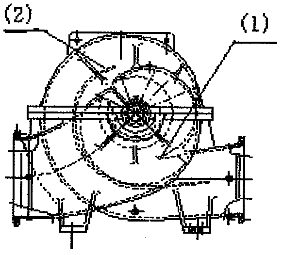
[0011] Such as Figure 5 Shown, described a kind of double-suction volute chamber split centrifugal pump presses out chamber hydraulic diagram according to the following steps:

[0012] (1) According to the design parameters of the water pump, calculate the cross-sectional dimensions of (1~8) of the flow channel.

[0013] (2) Calculate and determine the position of the tongue (1) according to the ratio of rotation.

[0014] (3) Another tongue (2) is set at a position 180° away from the tongue (1) and at a position where the circumference radius is equal.

[0015] (4) Make (1-4) cross-sectional views from the tongue (1) respectively.

[0016] (5) start to make (5~8) cross-sectional diagrams from the tongue (2), these sections are both inner and outer double runners, and all design parameters of the inner runners will be exactly the same as those corresponding to the 180° angle. The net cross-sectional area of ​​the outer flow channel is equal to the calculated (5-8) cross-se...


PUM


Abstract

The invention relates to the technical field of water pumps, in particular to a centrifugal pump formed in a double-suction volute chamber. According to the centrifugal pump formed in the double-suction volute chamber, two flow channels are arranged in a pressured volute chamber; a separation tongue is respectively arranged at the symmetrical positions of the volute chamber, where central angles of the two flow channel are mutually 180 degrees; all parameters and the shapes of the two flow channels are completely consistent, so that the impeller can generate radial forces with the same size and opposite directions at the symmetrical position of 180 degrees in the center of the impeller during work; and due to the opposite directions, the two radial forces mutually offset and further the action of eliminating the radial forces is achieved.

Description


Claims


Application Information

Patent Timeline
Owner 周游
Features
  • R&D
  • Intellectual Property
  • Life Sciences
  • Materials
  • Tech Scout
  • Unparalleled Data Quality
  • Higher Quality Content
  • 60% Fewer Hallucinations
Learn More