
Rotor for modulated pole machine

A technology for modulated pole motors and rotors, applied in electrical components, electromechanical devices, electric components, etc., can solve problems such as undesired deformation, strength problems, complexity of individual components and increased cost, and achieve low-cost geometric structure, easy The effect of assembly

Inactive Publication Date: 2012-10-24
HOGANAS AB
View PDF6 Cites 4 Cited by
  • Summary
  • Abstract
  • Description
  • Claims
  • Application Information

AI Technical Summary

Problems solved by technology

But this approach leads to increased complexity and cost of individual components
Furthermore, it is difficult to achieve good overall tolerances, as components exhibit large variations in cross-sectional area, which can lead to undesired deformations such as bowing during heat treatment
Thin integrated bridge sections can also cause strength issues during assembly, especially if the structure must deform slightly during assembly to meet geometric tolerances

Method used


Image

  • Rotor for modulated pole machine
  • Rotor for modulated pole machine
  • Rotor for modulated pole machine

Examples


Embodiment Construction

[0086] In the following description, reference is made to the accompanying drawings, which show by way of example how the invention may be practiced.

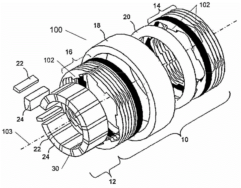
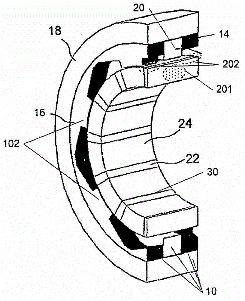
[0087] The invention relates to the field of modulated pole electric machines 100, an example of which is shown in a schematic exploded perspective view in Fig. 1a. The stator 10 of the modulated pole machine is basically characterized by the use of a central single winding 20 magnetically feeding a plurality of teeth 102 formed in a soft magnetic core structure. The stator core is then formed around windings 20 which, for other common motor configurations, are formed around individual tooth core sections. Examples of modulated pole motor layouts are sometimes referred to as claw pole, chicken claw, Rundle or TFM motors. More specifically, the illustrated modulated pole machine 100 includes two stator core sections 14, 16 (each section includes a plurality of teeth 102 and is substantially circular), A coil 20 arranged betwee...


PUM


Abstract

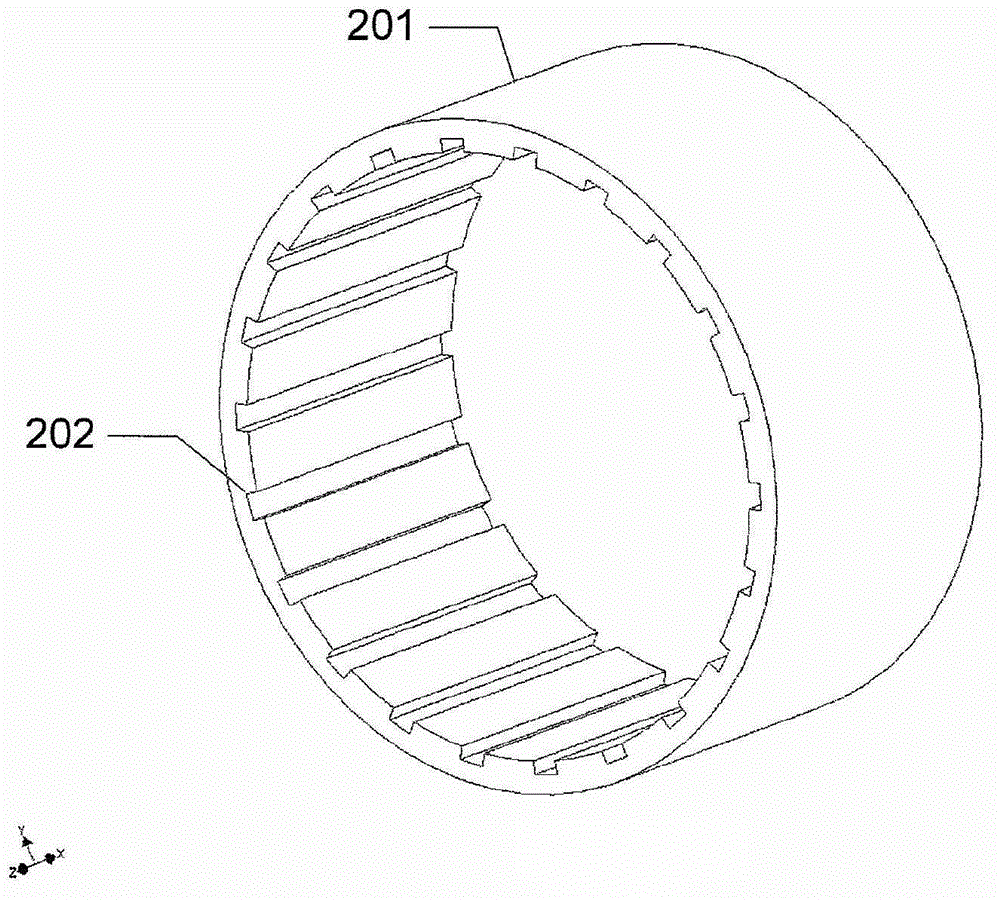
A rotor for a modulated pole machine, the rotor being configured to generate a rotor magnetic field for interaction with a stator magnetic field of a stator of the modulated pole machine, wherein said rotor comprises: a tubular support structure defining (201, 301) a circumferential mounting surface, the tubular support structure comprising a plurality of elongated recesses (202) in the mounting surface, the elongated recesses extending in an axial direction of the tubular support structure and a plurality of permanent magnets (203) arranged at the mounting surface of the tubular support structure and magnetised in the circumferential direction of said rotor so as to generate the rotor magnetic field, the permanent magnets (203) being separated from each other in the circumferential direction of the rotor by axially extending rotor pole sections (204); for directing the rotor magnetic field generated by said permanent magnets in a radial direction, wherein at least one permanent magnet (203) or one rotor pole section (204) extends at least partly into one of the plurality of recesses.

Description

technical field [0001] The present invention relates to a rotor of a modulated pole electric machine, more particularly, the present invention relates to a rotor of a modulated pole electric machine which can be easily mass-produced. Background technique [0002] Over the years, motor designs such as modulated pole machines, claw pole machines, Lundell machines, and transverse flux machines (TFM) have become more and more interesting. Electric machines using these motor principles were first disclosed by Alexandersen and Fessenden around 1910. An important reason for the increased interest is that the design allows for extremely high torque outputs of, for example, induction motors, switched reluctance motors, and even permanent magnet brushless motors. Further, these motors are advantageous because the coils are easy to manufacture. However, one disadvantage of this design is that manufacturing costs are generally relatively high, and there is high leakage flux leading to...

Claims


Application Information

Patent Timeline
Patent Type & Authority Applications(China)
IPC IPC(8): H02K1/27
CPCH02K2201/12H02K1/2786H02K1/2773H02K1/2791H02K1/27
Inventor L-O·彭纳德G·诺德
Owner HOGANAS AB
Learn More