Clamp type self-lock equipment

A self-locking device and clamp-type technology, used in seat belts, life-saving equipment and other directions, can solve the problem of insufficient self-locking effect and other problems, and achieve reliable self-locking effect and reliable self-locking effect.

Active Publication Date: 2014-11-19
CHINA ENERGY ENG GRP GUANGDONG ELECTRIC POWER DESIGN INST CO LTD
View PDF8 Cites 0 Cited by
  • Summary
  • Abstract
  • Description
  • Claims
  • Application Information

AI Technical Summary

Problems solved by technology

At present, most of the self-locking devices at home and abroad simply use the rocker arm to drive the brake block to achieve self-locking, and the effect of self-locking is not reliable enough.

Method used


Image

  • Clamp type self-lock equipment
  • Clamp type self-lock equipment
  • Clamp type self-lock equipment

Examples


Embodiment Construction

[0033] Embodiments of the present invention are described in detail below:

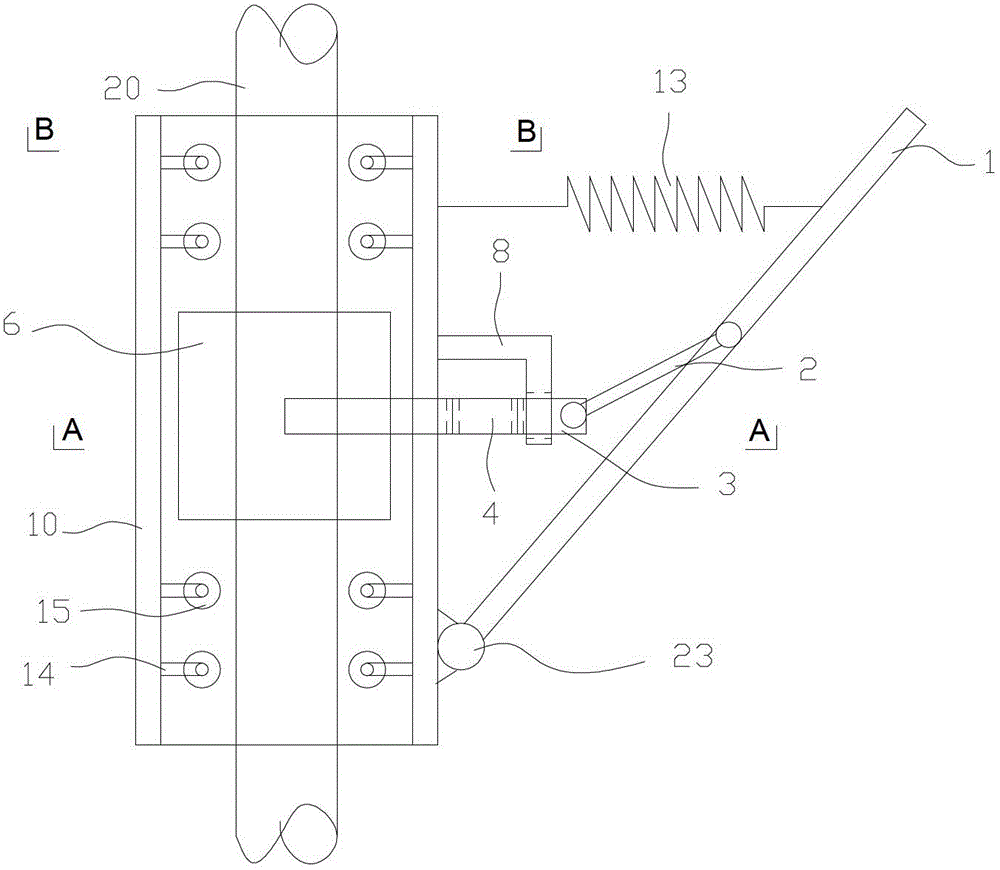
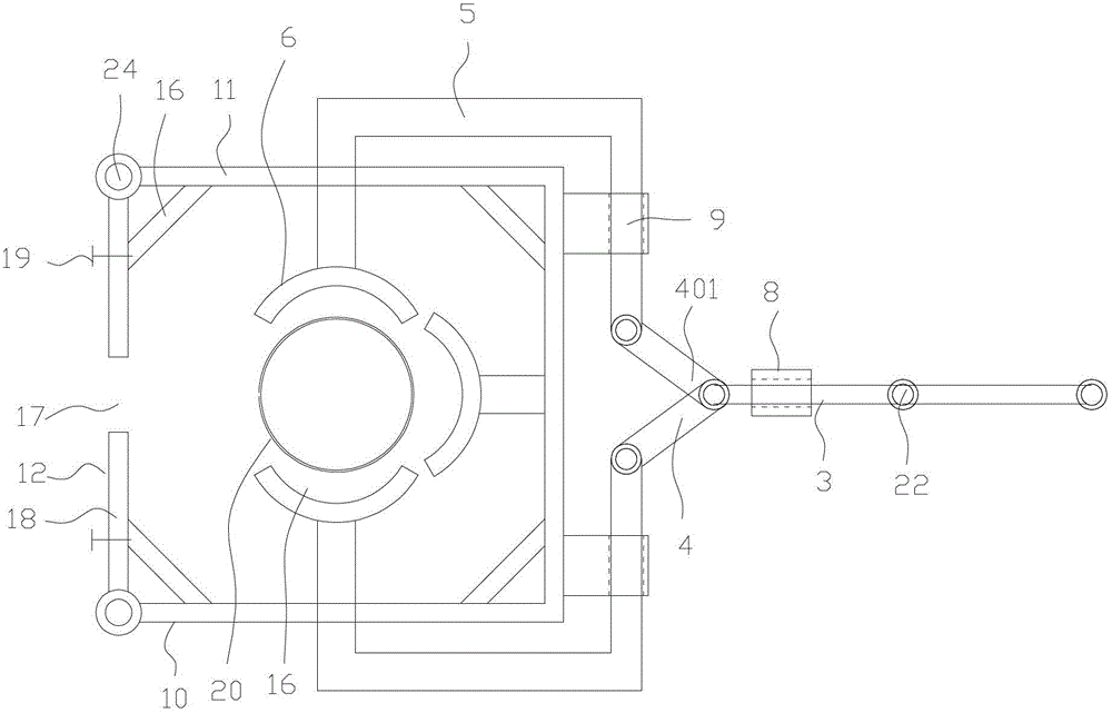
[0034] Such as Figure 1-2 As shown, a pincer type self-locking device includes a housing 10, a connecting rod transmission structure and a force component transmission structure. The housing 10 is provided with a fixed housing wall 11 and a movable housing wall 12. The rod transmission structure includes a rocker arm 1, a steering link 2, a horizontal link 3, a rocker shaft 23, a link shaft 22 and a horizontal sleeve 8. One end of the rocker arm 1 is movably connected to the On the outer wall of the fixed shell wall 11 opposite to the movable shell wall 12, one end of the steering link 2 is movably connected to the rocker arm 1, and the other end is connected to the first end of the horizontal link 3 through the link shaft 22. connection, the horizontal connecting rod 3 is covered with a horizontal sleeve 8, and the horizontal sleeve 8 is fixed on the outer wall of the fixed shell wall 11 opposite t...


PUM


Abstract

The invention discloses clamp type self-lock equipment which comprises a housing, a connecting rod transmission structure and a component force transmission structure, wherein the housing is provided with a fixed housing wall and a movable housing wall; the connecting rod transmission structure comprises a rocker arm, a steering connecting rod, a horizontal connecting rod and a horizontal sleeve, wherein one end of the rocker arm is connected to the outer wall of the fixed housing wall opposite to the movable housing wall; one end of the steering connecting rod is connected to the rocker arm, and the other end is movably connected with the first end of the horizontal connecting rod; the horizontal connecting rod is sleeved with the horizontal sleeve; the horizontal sleeve is fixed on the outer wall of the fixed housing wall opposite to the movable housing wall; the component force transmission structure comprises a scissor connecting rod, a movable clamp and a braking component, wherein one end of the scissor connecting rod is movably connected with the movable clamp, and the other end is movably connected with a second end of the horizontal connecting rod through a rotating shaft; and the braking component is fixedly connected to the end part of the movable clamp. Therefore, the clamp type self-lock equipment has a more reliable self-lock effect.

Description

technical field [0001] The invention relates to a fall prevention device, in particular to a clamp type self-locking device. Background technique [0002] Existing anti-falling devices for steel strands usually include components such as laces, safety ropes, connectors, and self-locking devices, wherein the self-locking device is the core component of this type of device. At present, most of the self-locking devices at home and abroad simply use the rocker arm to drive the brake block to realize self-locking, and the effect of self-locking is not reliable enough. Contents of the invention [0003] Based on this, the present invention overcomes the defects of the prior art and provides a pincer-type self-locking device whose self-locking effect is more reliable. [0004] Its technical scheme is as follows: [0005] A pincer type self-locking device, which includes a housing, a connecting rod transmission structure and a force component transmission structure, the housing ...

Claims


Application Information

Patent Timeline
Patent Type & Authority Patents(China)
IPC IPC(8): A62B35/00
Inventor 徐力何运祥谢荣坤李敏生黄炳权肖志军杨雅芬徐瑞崔磊梁德飞王蜂岚章冕颜耀麟黄龙湘
Owner CHINA ENERGY ENG GRP GUANGDONG ELECTRIC POWER DESIGN INST CO LTD
Why Eureka
Try Eureka