
A rubber tensile intelligent testing device and testing method thereof

A tensile testing and rubber technology, applied in the field of rubber tensile intelligent testing devices, can solve the problems of multiple disassembly and assembly, cumbersome replacement process, inaccurate test results, etc., to reduce impact inertia, improve efficiency, and simplify sample fixation. effect of the process

Active Publication Date: 2022-01-11
SHEN ZHEN SQUARE BOTTLE CO LTD
View PDF27 Cites 0 Cited by
  • Summary
  • Abstract
  • Description
  • Claims
  • Application Information

AI Technical Summary

Problems solved by technology

It not only provides daily and medical light industrial rubber products that are indispensable for people’s daily life, but also provides various rubber production equipment or rubber parts for mining, transportation, construction, machinery, electronics and other heavy industries and emerging industries. Materials and products have strict quality requirements, such as tensile strength, elastic modulus, elongation, aging resistance, etc. The tensile strength test of rubber can determine the tensile strength of rubber. At present, the tensile test of rubber mainly uses The rubber is made into a standard strip or I-shaped sample, and its two ends are fixed on the tensile machine for testing. However, the replacement process of each sample is cumbersome, and the internal sample fixture needs to be disassembled many times. During the test, the two ends of the rubber sample need to be tightly clamped and fixed. During the stretching process, the clamped part often breaks first, resulting in inaccurate test results.

Method used


Image

  • A rubber tensile intelligent testing device and testing method thereof
  • A rubber tensile intelligent testing device and testing method thereof
  • A rubber tensile intelligent testing device and testing method thereof

Examples


Embodiment Construction

[0037] The following will clearly and completely describe the technical solutions in the embodiments of the present invention with reference to the accompanying drawings in the embodiments of the present invention. Obviously, the described embodiments are only some, not all, embodiments of the present invention.

[0038]In describing the present invention, it should be understood that the terms "upper", "lower", "front", "rear", "left", "right", "top", "bottom", "inner", " The orientation or positional relationship indicated by "outside", etc. is based on the orientation or positional relationship shown in the drawings, and is only for the convenience of describing the present invention and simplifying the description, rather than indicating or implying that the referred device or element must have a specific orientation, so as to Specific orientation configurations and operations, therefore, are not to be construed as limitations on the invention.

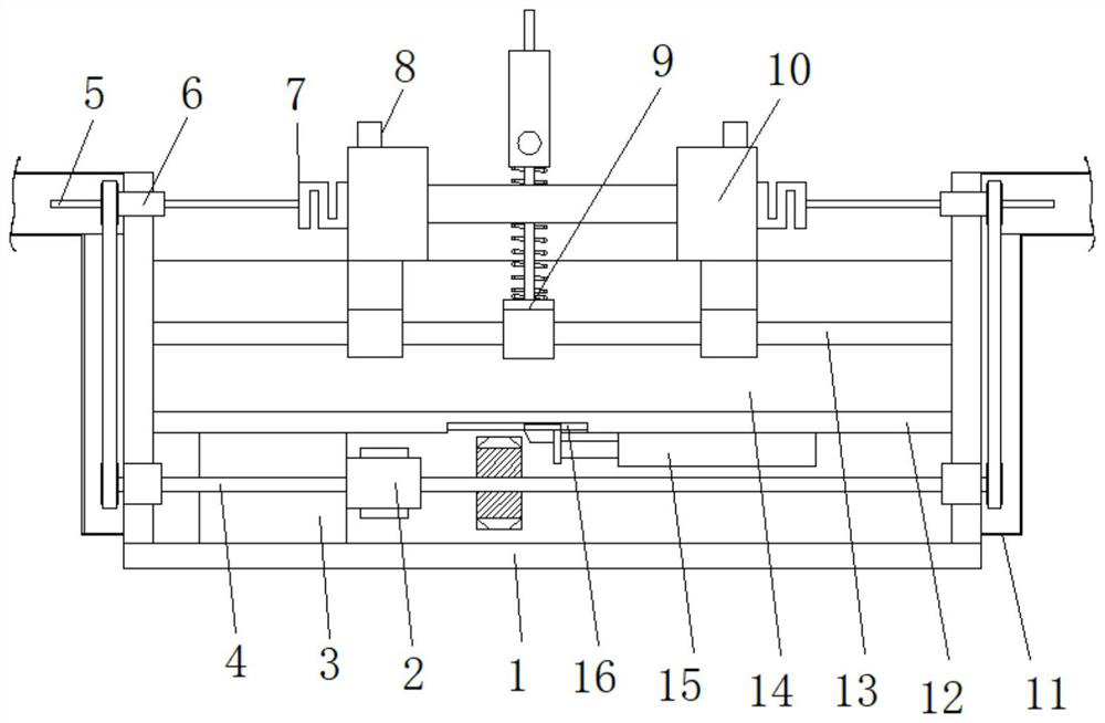
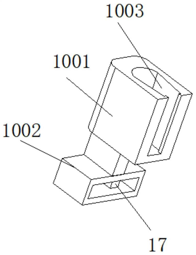
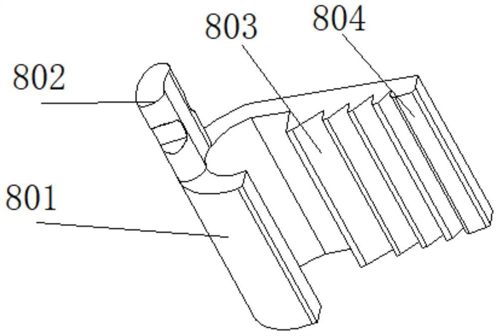
[0039] refer to Figure 1...


PUM


Abstract

The invention belongs to the technical field of the rubber industry, in particular to a rubber tensile intelligent testing device and a testing method thereof. The replacement process of the sample is cumbersome, and the internal sample fixture needs to be disassembled many times. Secondly, during the testing process, the rubber The two ends of the sample need to be tightly clamped and fixed. During the stretching process, the clamped part is often broken first, resulting in inaccurate test results. The following scheme is proposed, including the base, and the top of the base is fixedly installed with a support shell. In addition, a partition is fixedly installed in the middle of the inner wall of the support housing, and a test rotating shaft is installed at the inner bottom of the support housing through a bearing. The present invention can effectively reduce the impact inertia of the parts at both ends when the rubber strip is broken when performing tensile testing on the rubber strip sample. Secondly, the displacement control of the fixing seats at both ends is more accurate, and it can be more intuitive during the tensile test process. It can accurately observe the surface crack and tensile state of the sample, and improve the accuracy and safety of the test results.

Description

technical field [0001] The invention relates to the technical field of the rubber industry, in particular to an intelligent testing device for rubber stretching and a testing method thereof. Background technique [0002] Rubber refers to a highly elastic polymer material with reversible deformation. It is elastic at room temperature, can produce large deformation under a small external force, and can return to its original shape after the external force is removed. Rubber is a completely amorphous polymer. Rubber is divided into two kinds of natural rubber and synthetic rubber. Natural rubber is processed by extracting gum from rubber trees, rubber grass and other plants; synthetic rubber is obtained by polymerization of various monomers. Rubber products are widely used in all aspects of industry or life. [0003] The rubber industry is one of the important basic industries of the national economy. It not only provides daily and medical light industrial rubber products t...

Claims


Application Information

Patent Timeline
Patent Type & Authority Patents(China)
IPC IPC(8): G01N3/16G01N3/04G01N3/06
CPCG01N3/16G01N3/04G01N3/06G01N2203/0003G01N2203/0017G01N2203/005G01N2203/0037G01N2203/0075G01N2203/0262
Inventor 顾雪芬
Owner SHEN ZHEN SQUARE BOTTLE CO LTD
Learn More