Welding spot thrust detection device and method

A detection device and thrust technology, which is applied in the direction of measuring devices, using stable tension/pressure testing material strength, instruments, etc., can solve the problems of low detection accuracy of solder joint thrust, affecting product qualification rate, poor consistency, etc., to achieve testing High speed, good consistency, and high consistency of thrust

Active Publication Date: 2018-12-18
GOERTEK INC
View PDF9 Cites 0 Cited by
  • Summary
  • Abstract
  • Description
  • Claims
  • Application Information

AI Technical Summary

Problems solved by technology

[0007] In view of the above problems, the purpose of the present invention is to provide a solder joint thrust detection device and method to solve the problems of low precision, poor consistency, product scrapping risk and affecting product qualification rate in current products.

Method used


Image

  • Welding spot thrust detection device and method
  • Welding spot thrust detection device and method
  • Welding spot thrust detection device and method

Examples


Embodiment Construction

[0026] In the following description, for purposes of explanation, numerous specific details are set forth in order to provide a thorough understanding of one or more embodiments. It may be evident, however, that these embodiments may be practiced without these specific details. In other instances, well-known structures and devices are shown in block diagram form in order to facilitate describing one or more embodiments.

[0027] In order to describe in detail the structure of the solder joint thrust detection device of the present invention, specific embodiments of the present invention will be described in detail below with reference to the accompanying drawings.

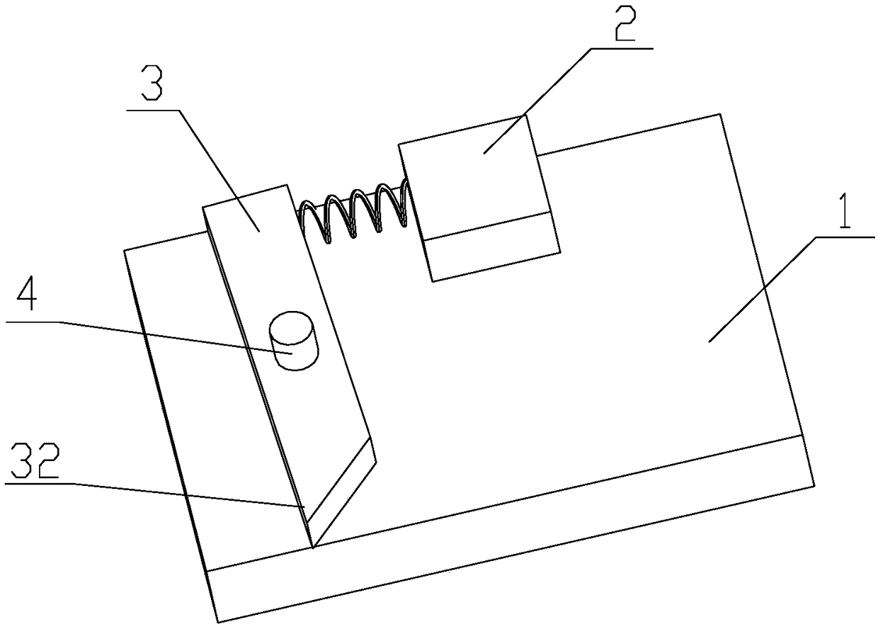
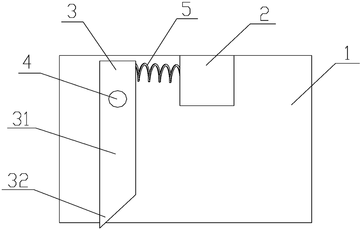
[0028] figure 1 and figure 2 The schematic structure of the solder joint thrust detection device according to the embodiment of the present invention is shown from different angles.

[0029] Such as figure 1 and figure 2 Commonly shown, the solder joint thrust detection device of the embodiment of the presen...


PUM


Abstract

The invention provides a welding spot thrust detection device and method. The welding spot thrust detection device comprises a manipulator, an executing mechanism and a thrust pen, wherein the executing mechanism and the thrust pen are arranged on the manipulator; the thrust pen is fixed to the manipulator through a rotating shaft; the executing mechanism is arranged on the side, away from a to-be-detected welding spot, of the thrust pen; the manipulator is used for driving the thrust pen to move to the side, close to the executing mechanism, of the to-be-detected welding spot; and the executing mechanism is used for pushing a pen holder of the thrust pen to rotate around the rotating shaft and horizontally pushing the to-be-detected welding spot through a pen point of the thrust pen. Through the welding spot thrust detection device and method, the detection quality of the welding spot can be improved.

Description

technical field [0001] The present invention relates to the technical field of product detection, and more specifically, to a device and method for detecting solder joint thrust. Background technique [0002] At present, in the quality inspection of the solder joints on the product, the detection method of the manipulator and the thrust test pen is generally used. Among them, a plurality of thrust test pens with position sensors are set on the manipulator, and the thrust test pen is driven by the manipulator for butt welding. Click for thrust test. [0003] However, due to the large differences in the size, position and height of different solder joints, their consistency cannot meet the precision requirements of the manipulator, resulting in a high failure rate of product inspection. The existing solder joint thrust detection methods mainly have the following defects: [0004] 1. Due to the position uncertainty between the detection solder joints and the randomness in spa...

Claims


Application Information

Patent Timeline
Patent Type & Authority Applications(China)
IPC IPC(8): G01N3/08G01N3/02
CPCG01N3/02G01N3/08G01N2203/0019G01N2203/0296G01N2203/0676
Inventor 刘佃国庞浩光
Owner GOERTEK INC
Why Eureka
Try Eureka