Insert cutter

A cutting tool and plug-in technology, used in milling cutters, forming knives, manufacturing tools, etc., can solve the problems of insufficient cutting edge strength and lack of cutting edge, and achieve the effect of optimized force deflection and firm positioning

Inactive Publication Date: 2015-09-30
CERATIZIT AUSTRIA GES
View PDF6 Cites 0 Cited by
  • Summary
  • Abstract
  • Description
  • Claims
  • Application Information

AI Technical Summary

Problems solved by technology

In addition, plunger cutting tools do not have a surrounding cutting edge chamfer, so the strength of the cutting edge is often insufficient, especially in the milling of steps and shoulders

Method used


Image

  • Insert cutter
  • Insert cutter
  • Insert cutter

Examples


Embodiment Construction

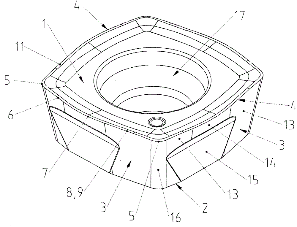
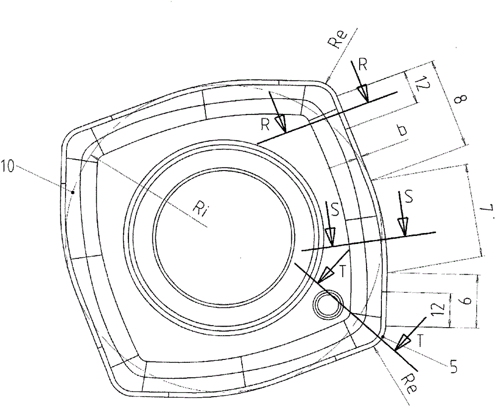
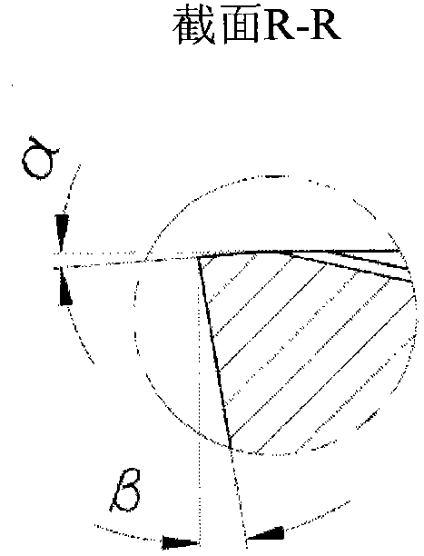
[0024] figure 1 and figure 2 , respectively a perspective view and a plan view, showing an insert cutting tool according to the invention having a square basic shape. The plunger cutting tool has a top face 1 , a bottom face 2 and a raised side face 3 inclined relative to the top face 1 at a clearance angle β. A raised cutting edge 4 is formed at the intersection between the top face 1 and the side face 3 . Each cutting edge 4 has a straight wiper edge 6 adjacent a cutting corner 5 . The wiper edge 6 then merges with the circular portion 7 into the main cutting edge 8 consisting of a straight portion 9 . The radius of the circular portion 7 is 70% of the radius Ri of the inscribed circle 10 . The theoretical circle that is inscribed in the top face 1 of the plunger cutter and touches all four cutting edges 4 is called the inscribed circle 10 . In the present case, the main cutting edge consists of a single straight portion 9 , but variants with up to three such straight ...


PUM


Abstract

A cutting insert with a substantially triangular or square basic form is particularly suited for face milling at high feed rates. It has convex cutting edges, which are each made up of a circular arc and at least one straight portion. Each cutting edge has, adjoining a cutting corner, a straight face cutting edge that merges with a main cutting edge, having 1 to 3 straight portions, a circular portion with a radius of at most 80% of the radius Ri of the inscribed circle. The cutting edges have an all-round cutting edge chamfer with a chamfer angle α. This chamfer angle α has along the cutting corners a value in the range from −10° to −20° and changes continuously along sub-portions of the face cutting edge and main cutting edge and along the circular portion to a constant value in the range from 0° to −10°.

Description

technical field [0001] The invention relates to insert cutting knives having a substantially triangular or square basic shape, the top and bottom of which are connected to each other by side faces, in which three or respectively four Each of the cutting edges—convex as seen in plan—is formed by the intersection between the top surface and the side surface and / or between the bottom surface and the side surface, each of which is defined by at least one arc and at least one A substantially straight section is formed and connected to each other via cut corners having a corner radius Re. Background technique [0002] The aforementioned plunger cutter is described in EP 1 689 548 . These plunger cutters are mainly used for face milling at high feed rates of approximately 0.5 mm / tooth to 3 mm / tooth with small depths of cut of up to 2 mm in order to mill flat faces as efficiently as possible. Machining. [0003] In a preferred configuration of the plunger cutting tool according t...

Claims


Application Information

Patent Timeline
Patent Type & Authority Patents(China)
IPC IPC(8): B23C5/20
CPCY10T407/24Y10T407/235B23C5/202Y10T407/23B23C5/205B23C5/06B23C2200/326
Inventor P·布尔舍
Owner CERATIZIT AUSTRIA GES
Why Eureka
Try Eureka