Locking device

A technology of locking devices and locking blocks, which is applied in the direction of fixing devices, mechanical equipment, etc., and can solve problems such as inconvenient loading and unloading of goods

Active Publication Date: 2018-09-28
WUHAN MARINE MACHINERY PLANT
View PDF3 Cites 0 Cited by
  • Summary
  • Abstract
  • Description
  • Claims
  • Application Information

AI Technical Summary

Problems solved by technology

[0005] When the mechanical device is loading and unloading goods, there are certain positioning requirements along the direction of the track. When the mechanical device reaches the loading and unloading position, the traveling mechanism brakes. Usually the opening of the locking hook is arranged vertically downward. At this time, the locking hook will be locked when locked. A large force perpendicular to the track plane is generated on the locking groove, which will change the position of the mechanical device perpendicular to the track plane, causing inconvenience to cargo loading and unloading

Method used


Image

  • Locking device
  • Locking device
  • Locking device

Examples


Embodiment Construction

[0023] In order to make the object, technical solution and advantages of the present invention clearer, the implementation manner of the present invention will be further described in detail below in conjunction with the accompanying drawings.

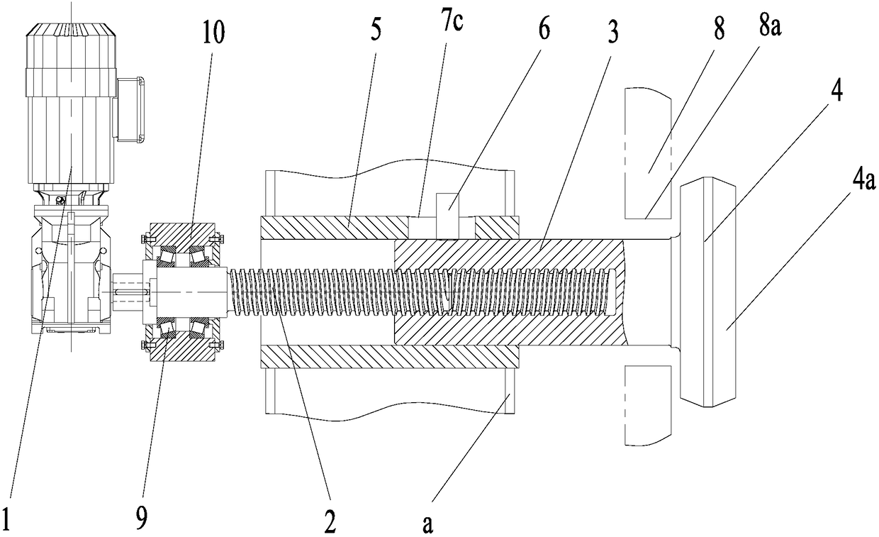
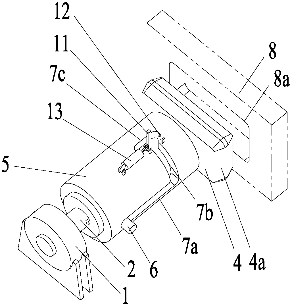
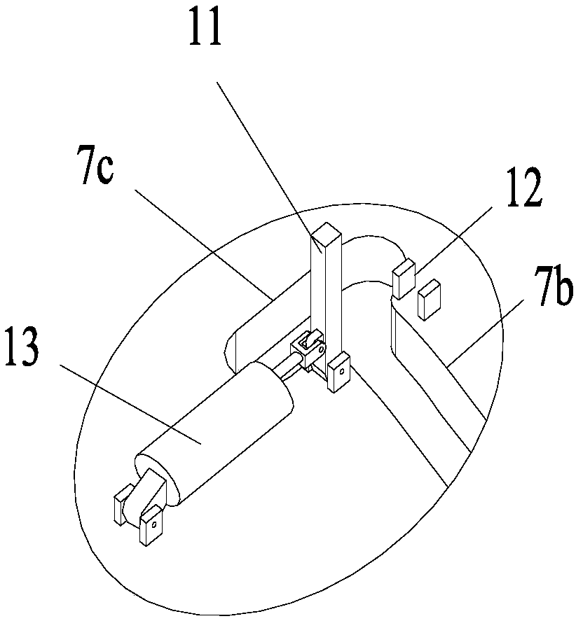
[0024] The embodiment of the present invention provides a locking device, such as figure 1 As shown, the locking device includes: a drive assembly 1, a screw 2, a screw sleeve 3, a locking block 4, a sliding sleeve 5 and a lock shaft 6, the transmission shaft of the drive assembly 1 is connected to the first end 2a of the screw 2, and the screw sleeve 3 Installed on the second end 2b of the screw rod 2 through threads, one end of the screw sleeve 3 is inserted in the sliding sleeve 5, the locking block 4 is arranged at the second end 2b of the screw rod 2, and the other end of the screw sleeve 3 protrudes from the sliding sleeve 5 It is fixedly connected with the locking block 4. Such as Figure 2 to Figure 4 As shown, the sliding sl...


PUM


Abstract

The invention discloses a locking device comprising a driving component, a screw rod, a screw rod sleeve, a locking block, a sliding sleeve and a locking shaft. A transmission shaft of the driving component is connected to the first end of the screw rod, and the screw rod sleeve is installed at the second end of the screw rod through threads; one end of the screw rod sleeve is inserted into the sliding sleeve, and the locking block is arranged at the second end of the screw rod; the other end of the screw rod sleeve extends out of the sliding sleeve, and is fixedly connected to the locking block, and the sliding sleeve is provided with a first sliding hole and a second sliding hole; the first sliding hole is formed in the axis direction of the sliding sleeve, and the second sliding hole isformed in the radial direction of the sliding sleeve; the first end of the first sliding hole communicates with the first end of the second sliding hole, and the first end of the sliding hole is theend close to the locking block; and the locking shaft is fixed to the outer wall of the screw rod sleeve, and slidably arranged in the first sliding hole and the second sliding hole. According to thelocking device, the locking is achieved through extension and retraction of the screw rod, and the action force generated by the screw rod in the locking process and the locking direction are consistent; and the action force in other directions is not generated.

Description

technical field [0001] The invention relates to the field of mechanical locking devices, in particular to a locking device. Background technique [0002] Locking devices are fitted in many mechanical devices that fit on tracks, such as ships, cranes or rail vehicles. When the mechanical device loads and unloads heavy goods, an impact force will be generated in the direction perpendicular to the track of the mechanical device. The impact force will cause the mechanical device to move. The locking device can prevent the mechanical device from moving in the direction perpendicular to the track. [0003] An existing locking device includes a hydraulic cylinder, a locking hook and a locking groove arranged on one side of the track, the cylinder body of the hydraulic cylinder and the hinged end of the locking hook are respectively hinged to the mechanical device, the piston rod of the hydraulic cylinder is hinged to the locking hook, and The hydraulic cylinder is configured to dr...

Claims


Application Information

Patent Timeline
Patent Type & Authority Applications(China)
IPC IPC(8): F16B1/04
CPCF16B1/04F16B2200/89
Inventor 胡茂陆兆鹏余峰蔡智军
Owner WUHAN MARINE MACHINERY PLANT
Why Eureka
Try Eureka