
Support device capable of self-locking for non-manpower vehicle

A technology of a bracket device and a vehicle, which is applied to the brackets of bicycles, bicycle accessories, transportation and packaging, etc., can solve the problems of poor anti-theft safety, labor-intensive, easy to be put away by others without authorization, and push the car away, and achieve stable landing. , support convenient effect

Active Publication Date: 2013-08-21
张隆
View PDF6 Cites 0 Cited by
  • Summary
  • Abstract
  • Description
  • Claims
  • Application Information

AI Technical Summary

Problems solved by technology

It is not only labor-intensive to prop up and put away the bracket by manpower, but also it is easy to be stowed away by others when the bracket is in the erected state, and the car will be pushed away, so the anti-theft security is poor

Method used


Image

  • Support device capable of self-locking for non-manpower vehicle
  • Support device capable of self-locking for non-manpower vehicle
  • Support device capable of self-locking for non-manpower vehicle

Examples


Embodiment Construction

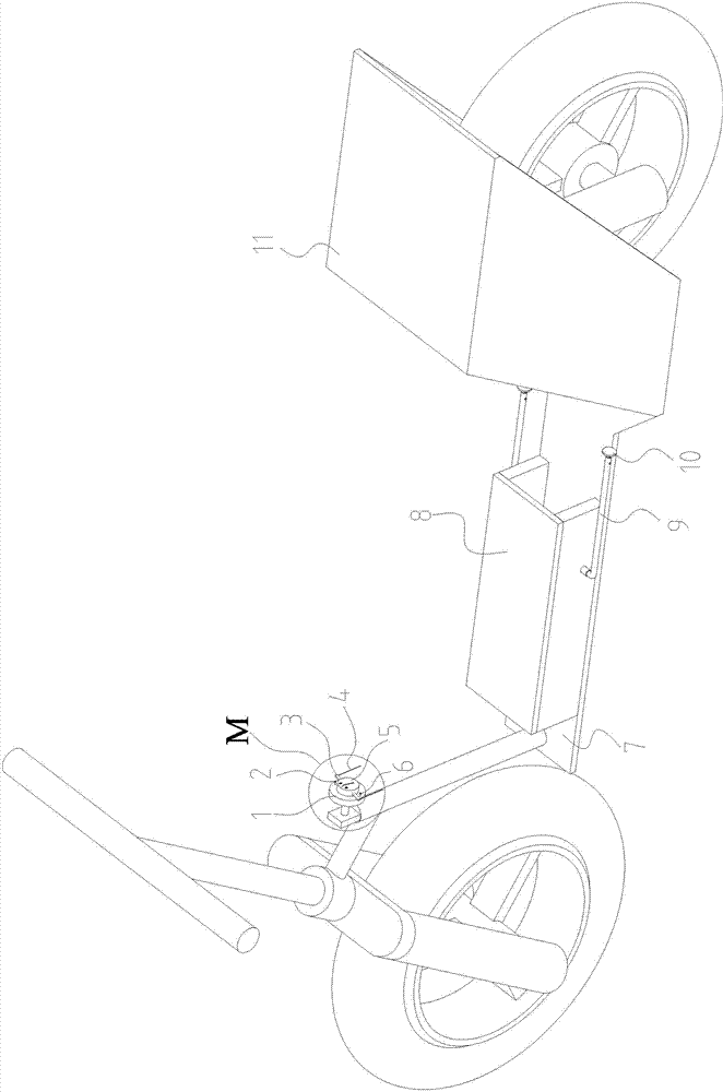
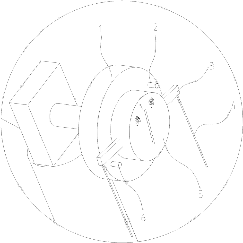
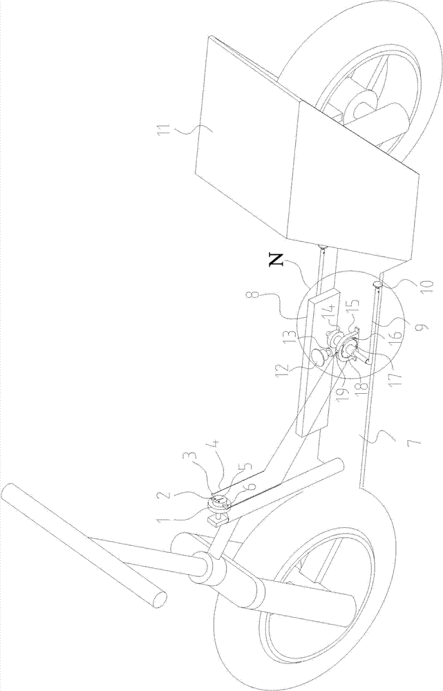
[0019] see Figure 1 to Figure 7 , the structure of this device is:

[0020] The car lock panel 1 is provided with a lock cylinder 5, and the pedal 7 of the vehicle body 11 is provided with a cabinet 8. The cabinet 8 is a rectangular structure, and the cabinet 8 is provided with a rotating shaft 14. This device preferably adopts a worm instead of the rotating shaft 14. The rotating shaft 14 is arranged on the vehicle body 11 parallel to the wheel axle, and the rotating shaft 14 is erected on the both sides of the cabinet 8. The two ends of the rotating shaft 14 are respectively fixedly connected with two brackets arranged outside the cabinet 8, and the two brackets are located at the bottom of the pedal 7. Outer side, cabinet 8 is provided with motor 12 on one side of rotating shaft 14, and motor 12 is vertically located on pedal 7, and motor 12 is connected with rotating shaft 14 by worm gear 13, and rotating shaft 14 is provided with rotating disk 18 far away from motor 12, ...


PUM


Abstract

Provided is a support device capable of self-locking for a non-manpower vehicle. A lock core is arranged on a vehicle lock panel. A machine case is arranged on a vehicle body pedal, a rotary shaft frame is arranged on the machine case, two ends of a rotary shaft are respectively and fixedly connected with two supports outside the machine case, the two supports are located on the outer side of thepedal, and a motor is arranged on one side of the rotary shaft in the machine case and is in matched connection with the rotary shaft through a transmission device. A turntable is arranged at the position of the rotary shaft away from the motor and installed in a turntable base in the machine case, a pair of centrosymmetric pin holes is arranged on the outer peripheral face of the turntable, a pair of through holes forming an angle of 90 degrees is arranged on the peripheral face of the turntable base, a first spring and a pin shaft are arranged in each through hole, two pin shafts are respectively connected with the ends of a shifting rod through flexible connecting shafts, the shifting rod is fixed on the lock core and rotates along with the lock core synchronously, a first trigger switch and a second trigger switch are arranged at two positions of the vehicle lock panel corresponding to the lock core, the switches are respectively and correspondingly matched with the two ends of the shift rod to as to control forward rotation and reverse rotation of the motor. The support device replaces manpower with motor driving to support or fold the supports, thereby saving time and labor.

Description

technical field [0001] The invention relates to a self-locking support device for a non-manpower vehicle. Background technique [0002] At present, the brackets used by non-manpower vehicles such as motorcycles and electric vehicles are placed in the support state by manpower when the vehicle is parked, and then the support is changed from the support state to stowed by manpower when the vehicle needs to drive. status, the vehicle is ready to drive. It is not only a lot of effort to prop up and put away the bracket by manpower, but also it is easy to be put away by others without authorization when the bracket is in the supported state, and the car is pushed away, so the anti-theft security is relatively poor. Contents of the invention [0003] The technical problem to be solved by the present invention is to provide a self-locking support device for non-human vehicles that saves time and effort. [0004] In order to solve the above-mentioned technical problems, the inve...

Claims


Application Information

Patent Timeline
Patent Type & Authority Patents(China)
IPC IPC(8): B62H1/02
Inventor 张隆
Owner 张隆
Learn More