Source driver and display apparatus

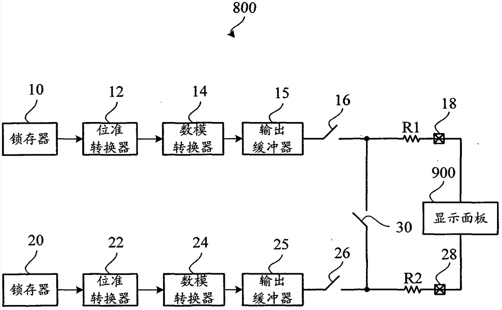
A source driver and display panel technology, applied in the electronic field, can solve the problems of reducing the ability of the display panel 900, reducing the speed of the display panel 900, etc.

Inactive Publication Date: 2012-11-07
FITIPOWER INTEGRATED TECH INC
View PDF9 Cites 7 Cited by
  • Summary
  • Abstract
  • Description
  • Claims
  • Application Information

AI Technical Summary

Problems solved by technology

[0007] Usually, the first switch 16 and the second switch 26 are both transistor switches, but the transistor switch is equivalent to a resistance when it is turned on, and the turn-on equivalent resistance of the tran

Method used


Image

  • Source driver and display apparatus
  • Source driver and display apparatus

Examples


Embodiment Construction

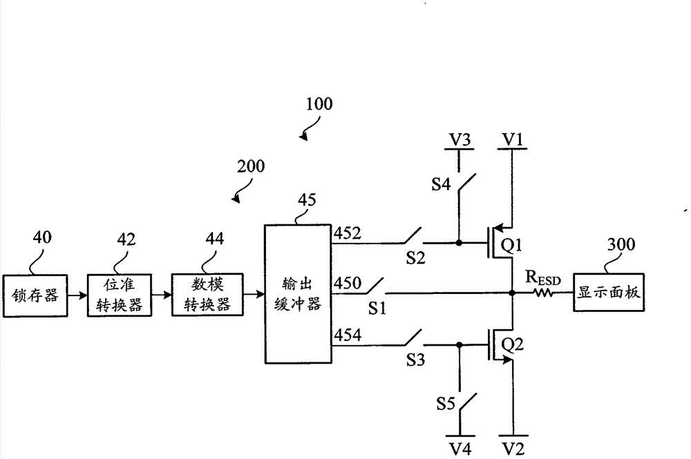
[0028] see figure 2 , a display device 100 in a preferred embodiment includes a source driver 200 and a display panel 300 . The source driver 200 is used for providing multiple driving voltages to the display panel 300 so that the display panel 200 displays image information.

[0029] The source driver 200 includes a latch 40, a level converter 42, a digital-to-analog converter 44, an output buffer 45, a first switch S1, a second switch S2, a third switch S3, a fourth switch S4, and a fifth switch S5, the first switch tube Q1, the second switch tube Q2, the electrostatic protection resistor R ESD .

[0030] The latch 40 is used to latch a plurality of digital display signals of one row, and the level converter 42 is used to convert the above-mentioned latched plurality of low-level digital display signals into a plurality of high-level digital display signals respectively, and The converted multiple digital display signals are provided to the digital-to-analog converter 44...


PUM


Abstract

A source driver includes an output buffer, a first switch, a second switch, a third switch, a first transistor, and a second transistor. The output buffer includes a first terminal for outputting a plurality of drive voltage to drive a display panel, a second terminal for outputting a first control signal, and a third terminal for outputting a second control signal. The first switch is connected between the first terminal and a display panel. The first transistor includes a first electrode connected to the second terminal via the second switch, a second electrode connected to a first power supply, and a third electrode connected between the first switch and the display panel. The second transistor includes a fourth electrode connected to the third terminal via the third switch, a fifth electrode connected to a second power supply, and a sixth electrode connected to the third electrode of the first transistor.

Description

technical field [0001] The invention relates to the field of electronic technology, in particular to a source driver and a display device. Background technique [0002] see figure 1 , which is a schematic diagram of a source driver 800 in the prior art, and the source driver 800 provides a driving voltage for the liquid crystal display panel 900 . The source driver 800 includes a first latch 10 and a second latch 20, a first level converter 12 and a second level converter 22, a first digital-to-analog converter 14 and a second digital-to-analog converter 24 , the first output buffer 15 and the second output buffer 25, the first switch 16 and the second switch 26, the first resistor R1 and the second resistor R2, the charge sharing switch 30, the first output terminal 18 and the second output terminal 28. The first switch 16 and the second switch 26 are turned on or off under the control of the first control signal; the charge sharing switch 30 is turned on or off under th...

Claims


Application Information

Patent Timeline
IPC IPC(8): G09G3/20
CPCG09G2310/0291G09G3/20G09G2310/0272
Inventor 许程琳李冠融
Owner FITIPOWER INTEGRATED TECH INC
Why Eureka
Try Eureka