
Method for producing piston rings

A technology of piston ring and piston pressure ring, applied in the field of piston pressure ring, can solve the problems of time-consuming and cost, and achieve the effect of saving time and cost

Inactive Publication Date: 2012-11-07
FEDERAL MOGUL BURSCHEID
View PDF9 Cites 6 Cited by
  • Summary
  • Abstract
  • Description
  • Claims
  • Application Information

AI Technical Summary

Problems solved by technology

[0003] The outer turning process for producing the always required contour of the outer circumferential surface is time-consuming and cost-intensive

Method used


Image

  • Method for producing piston rings

Examples


Embodiment Construction

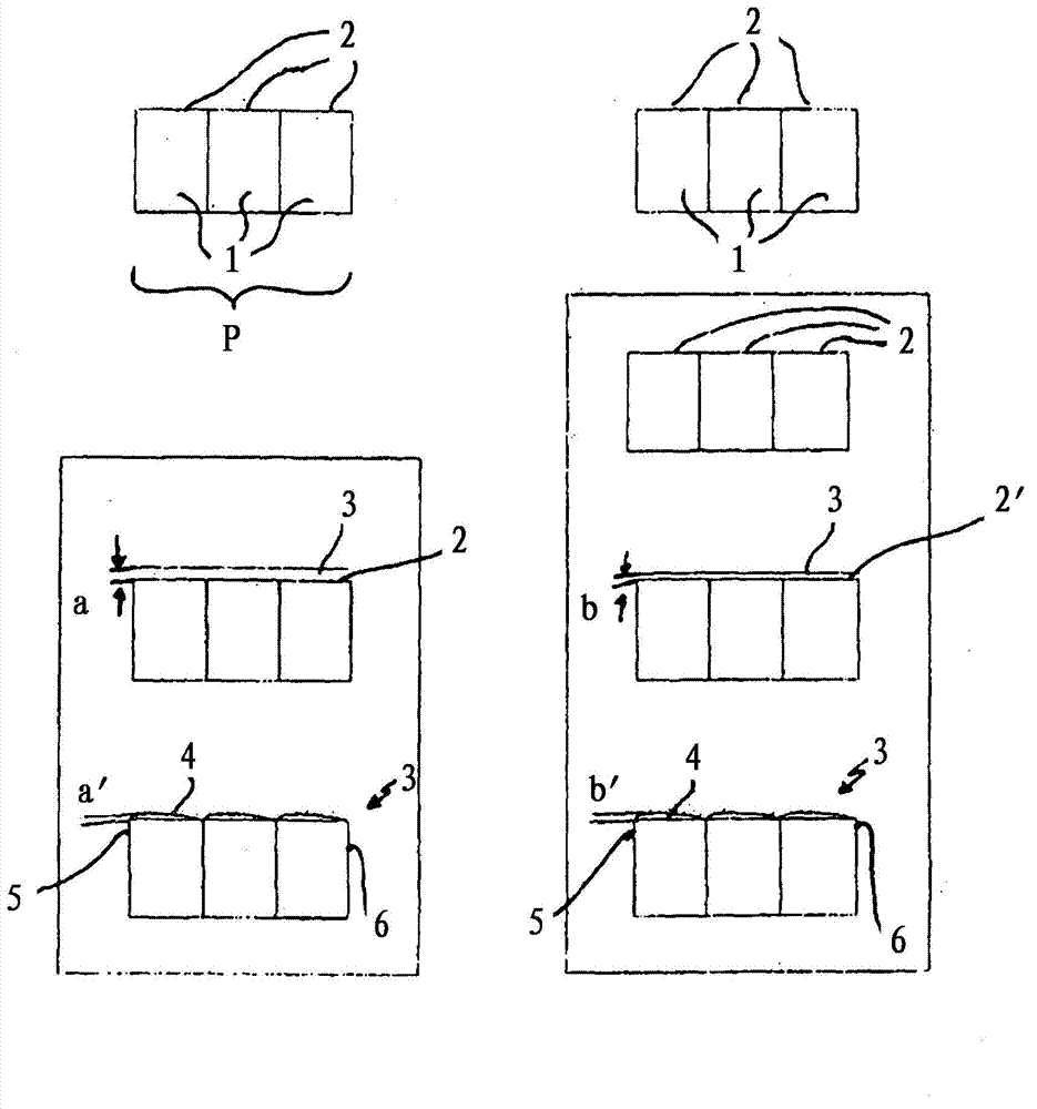
[0022] In the example on the left, an electroplated, wear-resistant chromium layer 3 of a predeterminable layer thickness a is applied directly to the cylindrical peripheral surface 2 . Now only the layer 3 is processed by means of a profile grinding tool (not shown) in such a way that a convex profile 4 is produced, which in this example has a maximum layer thickness a' in one of the working surface edge regions 5 , while the minimum layer thickness is provided towards the edge region 6 of the other working surface.

[0023] In the example on the right, the cylindrical profile turning is followed by a further machining process, namely cylindrical grinding, whereby the profile turned cylindrical peripheral surface 2 now forms material with a further minimal material removal. Another reduced cylindrical outer peripheral surface 2'. Similar to the example on the left, the outer circumferential surface 2 ′ now produced is provided with a galvanically produced, wear-resistant chr...


PUM


Abstract

A method for producing piston rings, in particular compression piston rings, in which at least one main element (1) is machined in such a way that a circumferential surface (2, 2') serving as a running surface is provided with a wear-resistant layer (3) of a predeterminable layer thickness (a, b), wherein a number of piston rings (1), in particular compression piston rings, brought together to form an assembly (P), are machined cylindrically in the region of their circumferential surface (2, 2'), a wear-resistant electrodeposited layer of chrome (3) is applied to the finished machined cylindrical circumferential surface (2, 2'), so that the wear-resistant layer (3) has a constant layer thickness within the assembly as a whole, and subsequently the layer (3) is machined in such a way as to produce a running surface (4) that has a region of maximum layer thickness and at least one region of minimum layer thickness.

Description

technical field [0001] The invention relates to a method for producing piston rings, in particular piston compression rings, according to the preamble of the first claim. Background technique [0002] Piston rings are often produced in such a way that they are cylindrically machined in the region of their outer circumference. Then, for example, by turning the outer circle, a desired contour, the so-called running surface contour, is produced. A wear-resistant layer, for example a chromium layer, is then applied to the predetermined non-cylindrical running surface contour, which deposits its deposits on the resulting contour and follows the same contour. The final working surface geometry is produced, for example, by circular grinding. In order to be able to carry out this process in a reasonable time and with the correct crown, the working surface must already have a profile which closely approximates that of the finished product. [0003] The rounding process for produci...

Claims


Application Information

Patent Timeline
Patent Type & Authority Applications(China)
IPC IPC(8): B23P15/06F16J9/26
CPCB23P15/06B23P13/02B23P17/02F16J9/26
Inventor D·巴伦罗伊特M·克尔纳
Owner FEDERAL MOGUL BURSCHEID
Learn More