
Beam adjusting mechanism of luggage rack

An adjustment mechanism and luggage rack technology, applied in the field of auto parts, can solve problems such as inflexible adjustment and inconvenient use, and achieve the effects of simple structure, improved work efficiency, and reasonable binding

Inactive Publication Date: 2012-11-14
江苏科达车业有限公司
View PDF0 Cites 0 Cited by
  • Summary
  • Abstract
  • Description
  • Claims
  • Application Information

AI Technical Summary

Problems solved by technology

In order to facilitate the loading of things, the car luggage rack has added a crossbeam, but the current crossbeam is generally fixed, and it cannot be flexibly adjusted according to the actual situation when tying luggage. It is inconvenient to use and needs to be improved.

Method used


Image

  • Beam adjusting mechanism of luggage rack
  • Beam adjusting mechanism of luggage rack

Examples


Embodiment Construction

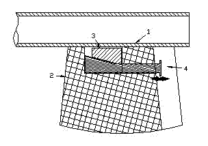
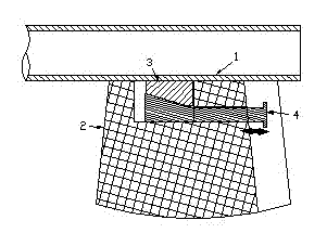
[0011] The present invention as figure 1 As shown, when in use, you only need to loosen the adjusting bolt 4, let the gravity of the locking block 3 act downward, reduce the friction between the locking block 3 and the beam 1, and facilitate the movement of the beam 1 in the direction specified by the beam slider 2 .

[0012] The locking state of the present invention is as figure 2 As shown, after adjusting the length of the beam 1, tighten the adjusting bolt 4, and the locking block 3 contacts the beam 1 upward under the action of the adjusting bolt 4 to increase the sliding friction force, and finally the locking block 3 clamps the beam 1.

[0013] The specific implementation above is only a preferred example of the present invention, and other structural forms that can adjust the contact pressure between the locking block and the gauge are also within the protection scope of the present invention.


PUM


Abstract

The invention relates to a beam adjusting mechanism of a luggage rack. The beam adjusting mechanism of the luggage rack comprises a beam and a beam slide block arranged at the lower part of the beam and blocked outside the beam. A locking block capable of lifting up and down is arranged at the lower part of the beam. The locking block is compactly contacted with the beam when lifting up. According to the beam adjusting mechanism, the way of frictional force between the beam and the locking block is changed by changing the contact pressure between the beam and the locking block so as to lock and unlock the beam, thereby achieving the acts of adjusting the beam twice. According to the beam adjusting mechanism of the luggage rack, luggage is bundled more reasonably and conveniently. Meanwhile, the beam adjusting mechanism of the luggage rack is simple in structure and convenient to operate, has extremely strong operability and improves the work efficiency.

Description

technical field [0001] The present invention relates to the improvement of automobile parts, in particular to an automobile luggage rack, and specifically relates to a luggage rack beam adjustment mechanism. Background technique [0002] With the continuous provision of modern people's living standards, outdoor travel needs to carry a lot of equipment and so on. In order to be able to load things conveniently, a crossbeam is added to the luggage rack of the car, but the crossbeam is generally fixed at present, and cannot be flexibly adjusted according to the actual situation when tying luggage, which is inconvenient to use and needs to be improved. Contents of the invention [0003] Aiming at the above problems, the present invention provides a luggage rack beam adjustment mechanism with simple structure, convenience and reliability. [0004] The technical solution of the present invention is: the present invention includes a crossbeam and a crossbeam slider arranged at t...

Claims


Application Information

Patent Timeline
Patent Type & Authority Applications(China)
IPC IPC(8): B60R7/08
Inventor 张洪贵张磊董永军
Owner 江苏科达车业有限公司
Learn More