
Current transformer (CT) coil lifting device

A hoisting device and coil technology, applied in the direction of transportation and packaging, load hanging components, etc., can solve the inconvenience of grasping and control, increase the risk of damage to the porcelain bushing of the high-voltage tank circuit breaker, and the difficulty of angle adjustment, etc. problem, to achieve the effect of improving the efficiency of the package and reducing the risk of the package

Active Publication Date: 2015-03-04
STATE GRID CORP OF CHINA +1
View PDF8 Cites 0 Cited by
  • Summary
  • Abstract
  • Description
  • Claims
  • Application Information

AI Technical Summary

Problems solved by technology

[0004] After the sling is used to directly fix the CT coil and the sling is hooked to the lifting equipment for hoisting, during the assembly process, the control of the CT coil angle must be realized by the operator directly by adjusting and controlling the CT coil, that is, the operator needs to directly It is inconvenient for the operator to grasp and control the circular contour of the CT coil set on the bushing, so this operation method brings difficulty to angle adjustment, which in turn increases the porcelain quality of the high-voltage tank circuit breaker. The risk of casing damage, so the above-mentioned method of directly fixing the CT coil with a sling has the disadvantages of high risk and low efficiency

Method used


Image

  • Current transformer (CT) coil lifting device
  • Current transformer (CT) coil lifting device
  • Current transformer (CT) coil lifting device

Examples


Embodiment Construction

[0029] In order to make the purpose, technical solutions and advantages of the embodiments of the present invention clearer, the technical solutions in the embodiments of the present invention will be clearly and completely described below in conjunction with the drawings in the embodiments of the present invention. Obviously, the described embodiments It is a part of embodiments of the present invention, but not all embodiments. Based on the embodiments of the present invention, all other embodiments obtained by persons of ordinary skill in the art without making creative efforts belong to the protection scope of the present invention.

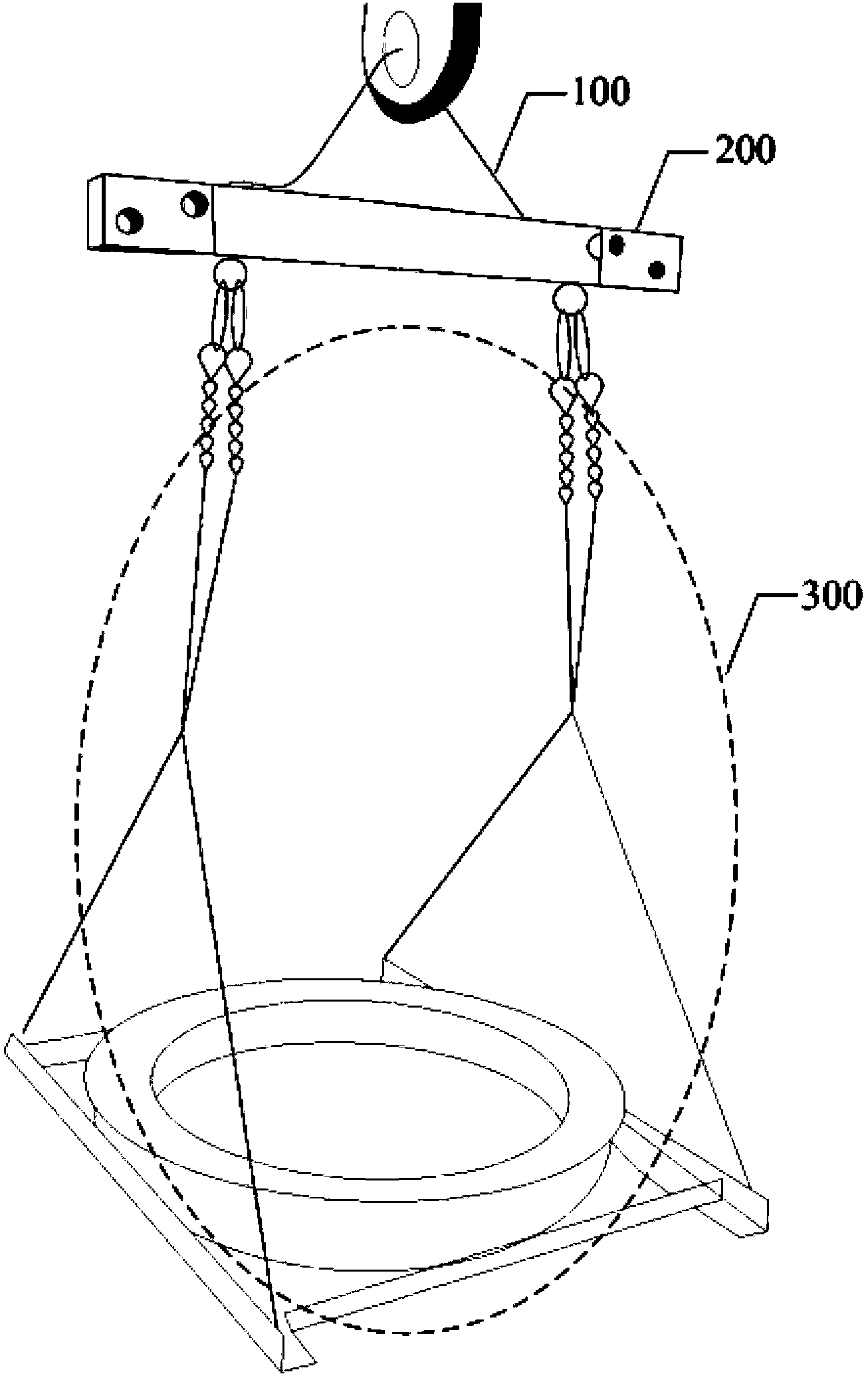
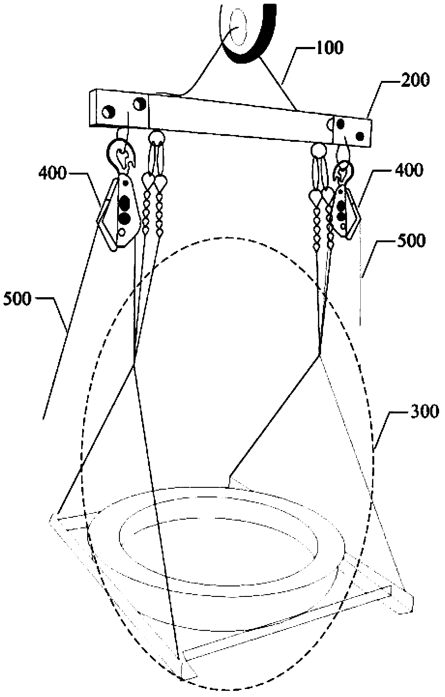
[0030] The invention discloses a CT coil hoisting device, which is used for hoisting the dry-type annular CT coil of a circuit breaker. Please refer to figure 1 , the CT coil lifting device includes a hanging ring 100, a hanging beam 200 and a fixing device 300, wherein:

[0031] The hanging ring 100 is connected with the hanging beam 200 an...


PUM


Abstract

The invention discloses a current transformer (CT) coil lifting device which comprises a hanging ring, a lifting beam and a fixing device. When a CT coil is placed on the fixing device to be fixed, only a short rope is required for firmly binding the CT coil and the fixing device; a lifting device can directly lift the CT coil and the fixing device through the hanging ring, the operation is simple, and the lifting is convenient; and when the CT coil is sleeved on an outer base portion of a casing pipe, angles of the CT coil can be adjusted by controlling the fixing device, so that a coil contour of the CT coil which is sleeved on the casing pipe can be prevented from being directly adjusted, difficulties of angle adjustment are reduced, and the risk that the porcelain casing pipe of a high voltage tank-type circuit breaker is damaged is reduced. Accordingly, the CT coil lifting device is capable of improving sleeving efficiencies and reducing sleeve installation risks.

Description

technical field [0001] The invention belongs to the technical field of hoisting devices, in particular to a CT (current transformer, current transformer) coil hoisting device. Background technique [0002] The expansion and transformation of the metering circuit of the high-voltage tank circuit breaker is the main project of the maintenance of the primary equipment of the substation. Added signal requirements for loops. In the process of expansion and transformation, it is necessary to install the newly added CT coil on the outer root of the bushing of the high-voltage tank circuit breaker. [0003] In the prior art, the newly added CT coil is installed on the outer root of the bushing of the high-voltage tank circuit breaker, and the specific method is as follows: the CT coil is directly fixed with a sling, and the sling hook is hung on the hook of the lifting device, so that The CT coil is hoisted by the sling, and then the CT coil is fitted manually to the outer root of...

Claims


Application Information

Patent Timeline
Patent Type & Authority Patents(China)
IPC IPC(8): B66C1/16
Inventor 马军张恩伟李永东林强刘树勇张慧于文博孔德国马楠宁卜翟博刘晨曦
Owner STATE GRID CORP OF CHINA
Learn More