Supercharge Your Innovation With Domain-Expert AI Agents!

Fluid flow control device

A control device, fluid flow technology, applied in valve devices, engine components, lift valves, etc., to solve problems such as pressure differences not being fully balanced, changes in inlet pressure and outlet pressure, etc.

Active Publication Date: 2014-12-03
FISHER JEON GAS EQUIP CHENGDU
View PDF9 Cites 0 Cited by
  • Summary
  • Abstract
  • Description
  • Claims
  • Application Information

AI Technical Summary

Problems solved by technology

This design requires an additional balanced spool element
Also, in actual operation, the inlet and outlet pressures adjacent to the valve disc may vary
Therefore, the relationship between the left and right sides of the above formula may deviate from the ideal relationship, so that the pressure difference cannot be fully balanced

Method used


Image

  • Fluid flow control device
  • Fluid flow control device
  • Fluid flow control device

Examples


Embodiment Construction

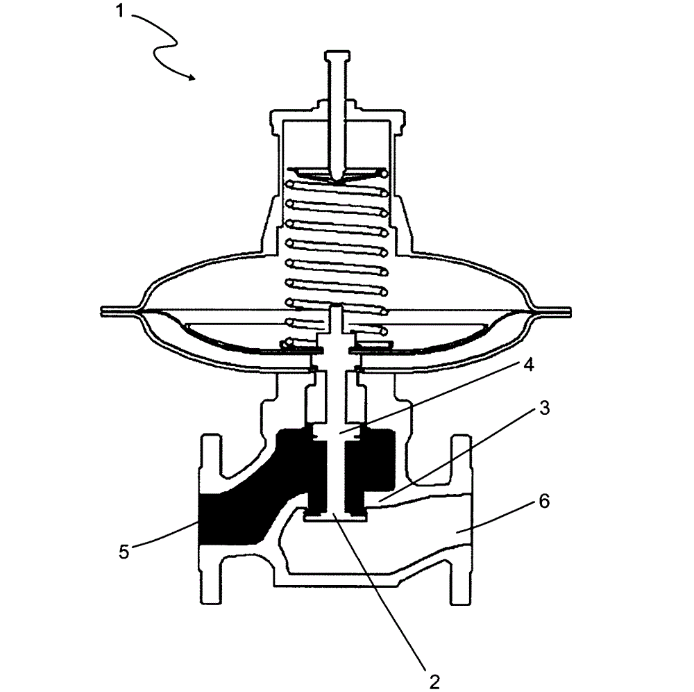
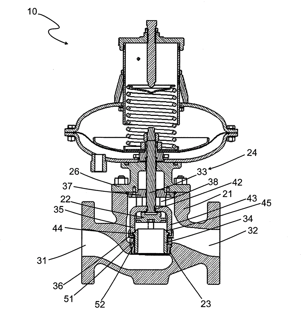
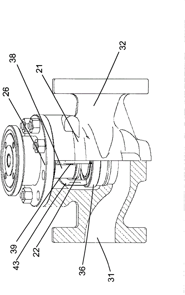
[0013] In the following detailed description of the preferred embodiment, reference is made to the accompanying drawings which form a part hereof. The accompanying drawings show, by way of example, specific embodiments in which the invention can be practiced. The illustrated embodiments are not intended to be exhaustive of all embodiments in accordance with the invention. It is to be understood that other embodiments may be utilized and structural or logical changes may be made without departing from the scope of the present invention. Accordingly, the following detailed description is not limiting, and the scope of the invention is defined by the appended claims.

[0014] In the following detailed description, reference is made to the accompanying drawings. The accompanying drawings, which constitute a part of this invention, show by way of example specific embodiments in which the invention can be practiced. In this regard, directional terms such as "left", "right", "top"...


PUM


Abstract

The invention relates to a fluid flow control device, which comprises a body, a valve disc, a guide element and a valve stem component, wherein the body is provided with an inlet and an outlet; the valve disc is fixedly arranged in the body; the guide element is positioned between the inlet and the outlet and is fixedly arranged in the body, the guide element comprises a cylindrical wall, and the cylindrical wall is provided with an inner surface and an outer surface; and the valve stem component comprises a valve stem, a sleeve and a support, and the valve stem is arranged in the body in a sliding way; the sleeve is provided with a first end and a second end which is opposite to the first end, the first end is provided with an edge which is used for connecting with the inner surface of the guide element in a sliding and sealing way, the second end is used for being selectively arranged between a first position and a second position, the second end is connected with the valve disc in a sealing way in the first position, and the second end is separated from the valve disc in the second position; and the support is used for coupling the sleeve to the valve stem.

Description

technical field [0001] The present invention relates generally to fluid flow control devices, and more particularly to valve trim. Background technique [0002] Many industries require regulator valves for controlling the pressure and flow of fluids. Regulator valves typically employ a movable disc that is used to engage or disengage a valve seat to control fluid flow through the valve. However, conventional regulator valves with a movable disc are generally affected by the pressure difference exerted on the disc by the inlet pressure and the outlet pressure. [0003] One known method for overcoming the effect of the pressure differential exerted on the valve disc by inlet and outlet pressures is to use a balanced spool. like figure 1 As shown, the regulating valve 1 includes a valve disc 2 , a valve seat 3 , a balanced spool element 4 , an inlet 5 and an outlet 6 . The balance spool element 4 is designed to provide such an ideal balance relationship: F 1 +F' 2 =F' 1 ...

Claims


Application Information

Patent Timeline
Patent Type & Authority Patents(China)
IPC IPC(8): F16K1/00F16K1/32F16K1/36F16K1/46
Inventor 霍羽雄霍平杨仲类彦威
Owner FISHER JEON GAS EQUIP CHENGDU
Features
  • R&D
  • Intellectual Property
  • Life Sciences
  • Materials
  • Tech Scout
  • Unparalleled Data Quality
  • Higher Quality Content
  • 60% Fewer Hallucinations
Learn More