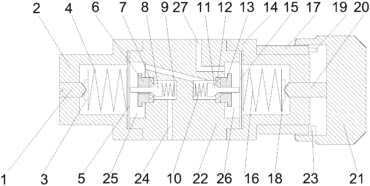
Constant pressure reducing valve

A pressure reducing valve and valve cover technology, applied in the field of constant pressure pressure reducing valves, can solve the problems of inability to close, unstable output pressure, and output flow changes, and achieve the effect of easy closing and opening, and stable output flow

Pending Publication Date: 2019-04-12
AEROTECH BEIJING
View PDF0 Cites 2 Cited by
  • Summary
  • Abstract
  • Description
  • Claims
  • Application Information

AI Technical Summary

Problems solved by technology

At present, there are many structural types of constant pressure relief valves, and the common one is the single-stage preset type. When not in use, because there is no pressure difference between the high and low pressure chambers of the pressure relief valve, the pressure relief valve remains open for a long time and cannot be closed; The pressure of the air source (high-pressure chamber) will continue to drop during use. In order to achieve a balanced state, the air pressure of the low-pressure chamber will rise with the drop of the air source pressure, resulting in unstable output pressure. Changes in the air source pressure and the pressure of the low-pressure chamber will cause output The flow rate changes; and there are problems that it cannot be closed, the output pressure is unstable, and the output flow is unstable

Method used


Image

  • Constant pressure reducing valve

Examples


Embodiment Construction

[0020] The following will clearly and completely describe the technical solutions in the embodiments of the present invention with reference to the accompanying drawings in the embodiments of the present invention. Obviously, the described embodiments are only some, not all, embodiments of the present invention. Based on the embodiments of the present invention, all other embodiments obtained by persons of ordinary skill in the art without making creative efforts belong to the protection scope of the present invention.

[0021] The purpose of the present invention is to provide a constant pressure relief valve to solve the above-mentioned problems in the prior art, to stabilize the output pressure and output flow, and to facilitate closing and opening of the constant pressure relief valve.

[0022] In order to make the above objects, features and advantages of the present invention more comprehensible, the present invention will be further described in detail below in conjuncti...


PUM


Abstract

The invention discloses a constant pressure reducing valve which comprises a valve body. The first end is provided with a primary low-pressure cavity and a primary transition cavity. The second end isprovided with a secondary low-pressure cavity and a secondary transition cavity. A gas inlet and a gas outlet are formed in the side wall of the valve body. The gas inlet, the primary transition cavity, the primary low-pressure cavity, the secondary transition cavity, the secondary low-pressure cavity and the gas outlet sequentially communicate. A primary pressure adjusting assembly is arranged on the communicating portion of the primary transition cavity and the primary low-pressure cavity. A secondary pressure adjusting assembly is arranged on the communicating portion of the secondary transition cavity and the secondary low-pressure cavity. A primary valve cover is connected with the first end. A primary pressure sensitive element is arranged between the primary valve cover and the first end. A primary valve cover elastic element is arranged in the primary valve cover cavity. A secondary valve cover is connected with the first end. A secondary pressure sensitive element is arrangedbetween the secondary valve cover and the first end. A secondary valve cover elastic element is arranged in the secondary valve cover cavity. A handle is fixedly connected with one end, extending outof the secondary valve cover, of a secondary ejection screw. The constant pressure reducing valve outputs pressure and flow stably and is convenient to be closed and opened.

Description

technical field [0001] The invention relates to the technical field of decompression valves, in particular to a constant pressure decompression valve. Background technique [0002] Pressure reducing valves are widely used in laboratories, electronic semiconductors, biomedicine, petroleum, petrochemical, gas, electric power, chemical industry, aerospace, solar energy and other fields. It is a valve that makes the medium pressure meet the pressure requirements required by the production process. At present, there are many structural types of constant pressure relief valves, and the common one is the single-stage preset type. When not in use, because there is no pressure difference between the high and low pressure chambers of the pressure relief valve, the pressure relief valve remains open for a long time and cannot be closed; The pressure of the air source (high-pressure chamber) will continue to drop during use. In order to achieve a balanced state, the air pressure of the ...

Claims


Application Information

Patent Timeline
Patent Type & Authority Applications(China)
IPC IPC(8): F16K17/30
CPCF16K17/30
Inventor 耿德占王大钊
Owner AEROTECH BEIJING
Why Eureka
Try Eureka