Electrohydraulic inverse proportion pressure reducing valve

An inverse proportional, pressure-reducing valve technology, applied in the field of hydraulic control, can solve the problems of complex valve cavity processing and difficult valve core assembly, and achieve the effects of high control accuracy, low manufacturing cost, and reduced repetitive labor.

Active Publication Date: 2018-03-23
BEIJING INSTITUTE OF TECHNOLOGYGY
View PDF7 Cites 2 Cited by
  • Summary
  • Abstract
  • Description
  • Claims
  • Application Information

AI Technical Summary

Problems solved by technology

In addition, it also solves the problems of complex processing of the valve cavity and difficult assembly of the valve core in the prior art

Method used


Image

  • Electrohydraulic inverse proportion pressure reducing valve
  • Electrohydraulic inverse proportion pressure reducing valve
  • Electrohydraulic inverse proportion pressure reducing valve

Examples


Embodiment 1

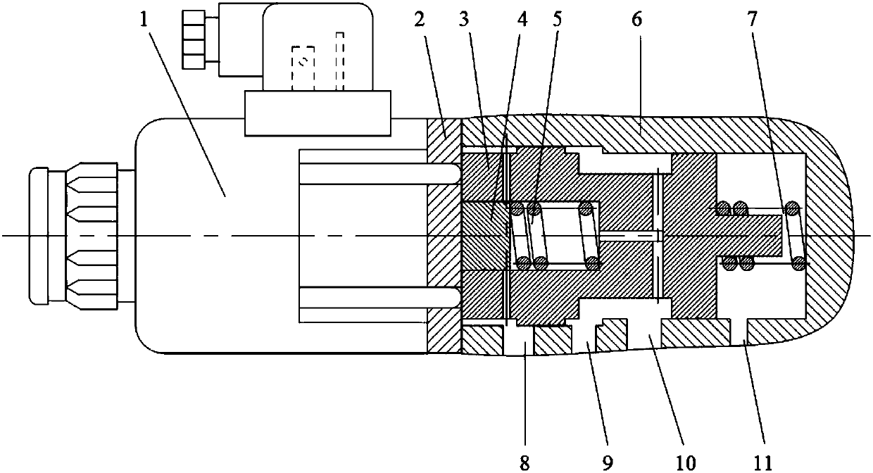
[0040] Such as figure 1 As shown, an electro-hydraulic inverse proportional pressure reducing valve of the present invention includes: a proportional electromagnet 1, a baffle plate 2, a valve core 3, a cylindrical plug 4, a first return spring 5, a valve body 6, and a second return spring 7; The valve body 6 is a bottom-sealed hollow stepped cylindrical cavity; the side wall is provided with an oil return port 8, an oil inlet port 9, a working oil port 10, and an oil drain port 11; the first return spring 5 is placed in the working chamber Middle; the second return spring 7 is set on the boss of the spool 3 . The baffle plate 2 is a cylindrical structure with two through holes corresponding to the side wall of the spool 3; the proportional electromagnet 1 is connected to the side wall of the spool 3 through the through hole of the baffle plate 2 touch;

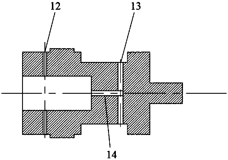
[0041] Such as figure 2 As shown, the valve core 3 is a cylindrical structure with a boss at one end; at the end away f...


PUM


Abstract

The invention relates to an electrohydraulic inverse proportion pressure reducing valve and belongs to the field of hydraulic control. The proportion pressure reducing valve comprises a valve body, avalve element, a cylinder plug, a first resetting spring, a second resetting spring, a proportion electromagnet and a baffle. A stepped valve cavity is adopted, when the electromagnet does not work, the work pressure output by the pressure reducing valve is maximum, along with increasing of current, the electromagnetic pushing force output by the electromagnet increases, the work pressure of the pressure reducing valve is gradually reduced, the hydraulic force in a work cavity of the valve element is balanced with the spring force and the electromagnetic force, and pressure adjusting of a hydraulic oil way is achieved. The structure of the pressure reducing valve is greatly simplified, and the production cost is reduced. The inverse proportion pressure reducing valve can improve the stability and the control precision of work of the system.

Description

technical field [0001] The invention relates to an inverse proportional pressure reducing valve, in particular to an electro-hydraulic inverse proportional pressure reducing valve, which belongs to the field of hydraulic control. Background technique [0002] The proportional pressure reducing valve is a control valve that uses the change of the electromagnetic coil to control the proportional electromagnet to realize the opening adjustment of the valve core of the pressure reducing valve. When the electromagnetic coil is energized, the electromagnetic force opens the valve core, and the hydraulic oil flows through the valve cavity to act on the surface of the valve core to generate pressure, which forms a force balance with the spring force and electromagnetic force, thereby controlling the pressure of the hydraulic oil circuit. Since the electromagnetic force of the proportional electromagnet is related to the energized current, the electromagnetic force can be adjusted st...

Claims


Application Information

Patent Timeline
Patent Type & Authority Applications(China)
IPC IPC(8): F15B13/02F16K31/06F16K11/065
CPCF15B13/021F16K11/0655F16K31/0668
Inventor 吴维刘辉苑士华胡纪滨
Owner BEIJING INSTITUTE OF TECHNOLOGYGY
Why Eureka
Try Eureka