
Novel controller for gas pressure regulator

A gas pressure regulator and controller technology, applied in the direction of functional valve types, safety valves, engine components, etc., can solve problems such as misoperation, pressure regulator fluctuations, output pressure fluctuations, etc., to prevent abnormal displacement, Guarantee the effect of output pressure and output pressure stability

Inactive Publication Date: 2012-08-15
TERRENCE ENERGY
View PDF5 Cites 2 Cited by
  • Summary
  • Abstract
  • Description
  • Claims
  • Application Information

AI Technical Summary

Problems solved by technology

[0003] The existing controllers for gas pressure regulators generally have the following types: The first type of controller has only one level of pilot. When the upstream pressure fluctuates, it is easy to cause the driving force for the main valve of the pressure regulator to be unstable, making the pressure regulation The outlet pressure of the gas regulator fluctuates; the second type of gas pressure regulator has two-stage controllers. Although there are two stages, the first stage does not have a design for feedback of downstream pressure. The output pressure of the first stage needs to be adjusted according to the set pressure. In use, it is necessary to adjust the output pressure of the first stage to the corresponding size first, and then adjust the second stage to adjust the output pressure of the regulator. Misoperation; the first-stage regulator of the controller for the third type of gas pressure regulator has a structure to feed back the downstream pressure, and the output pressure can be automatically adjusted with the change of the downstream pressure, and always maintain a fixed difference to the downstream pressure , so that a relatively stable pressure value can be output without manual adjustment, but the valve port of the regulator is affected by the inlet pressure and the output pressure of the regulator, and when the inlet pressure fluctuates, the output pressure fluctuates, causing fluctuations in the regulator

Method used


Image

  • Novel controller for gas pressure regulator
  • Novel controller for gas pressure regulator
  • Novel controller for gas pressure regulator

Examples


Embodiment

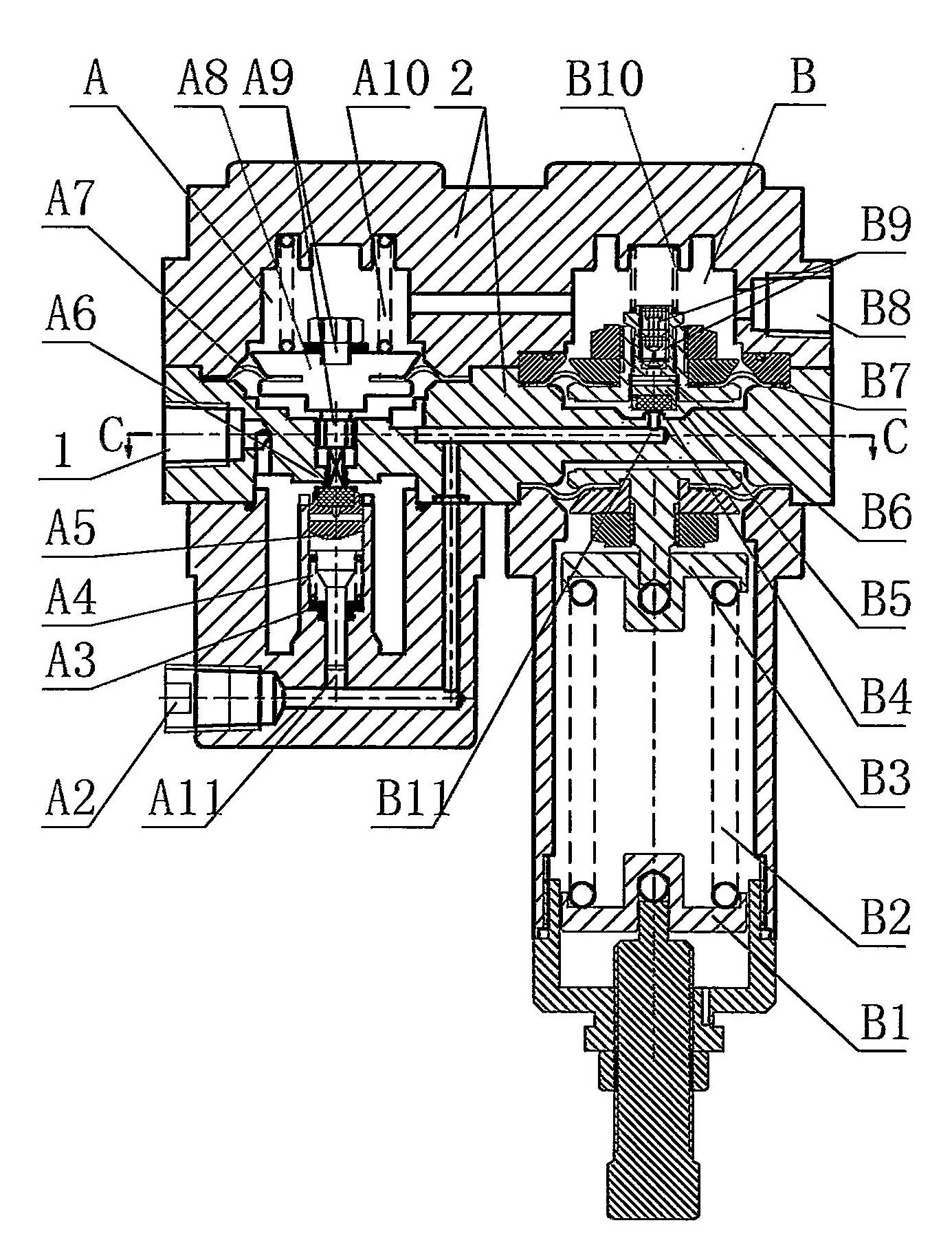
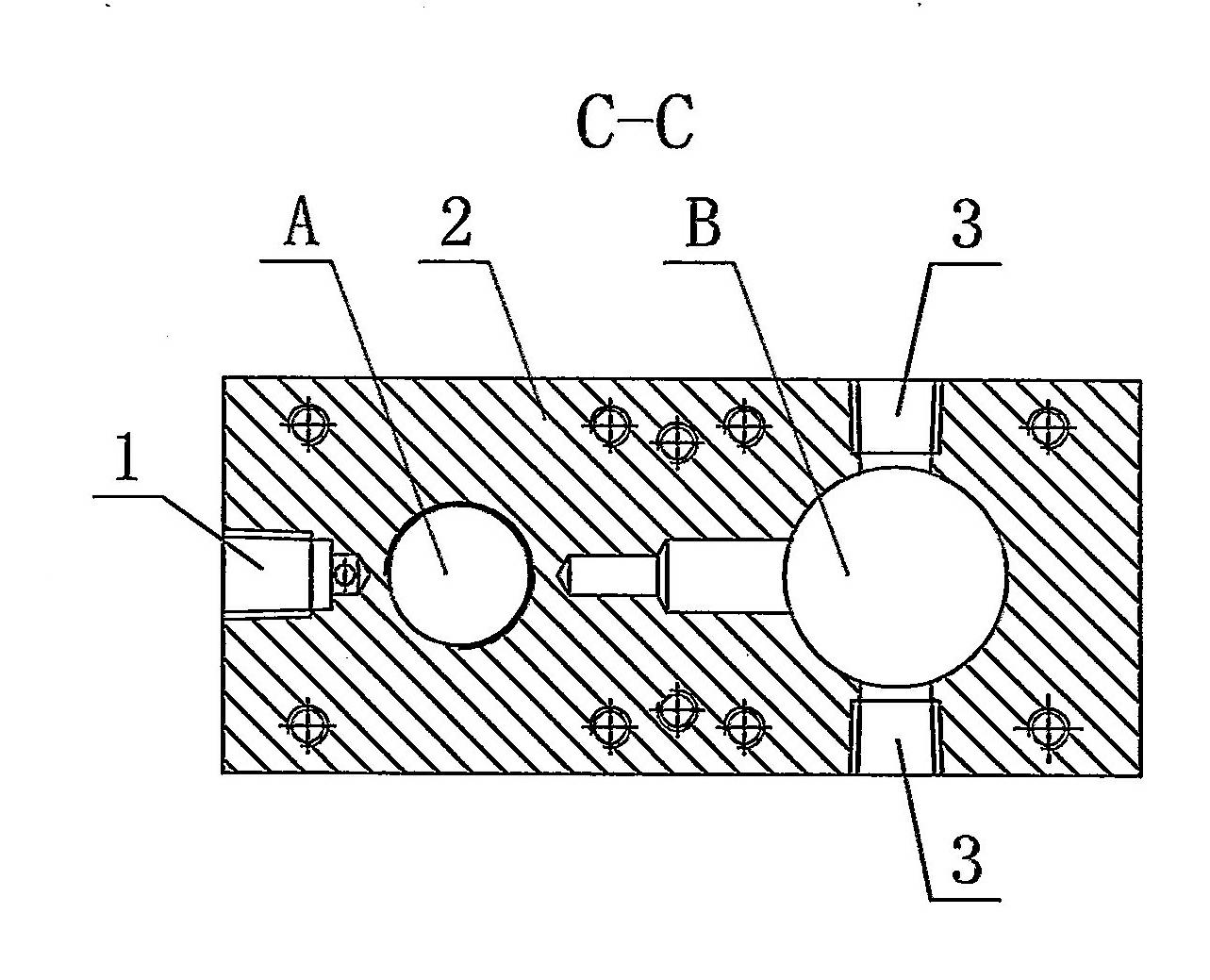
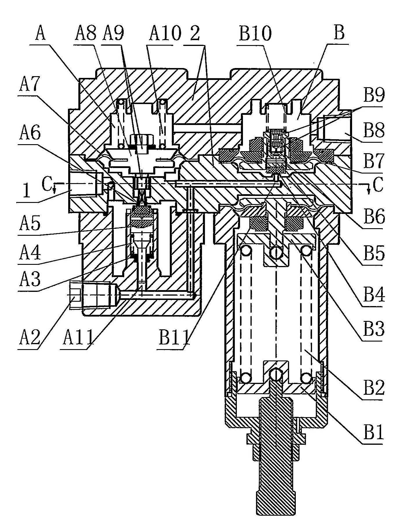
[0018] Such as Figure 1~2 As shown, a new type of controller for a gas pressure regulator includes an air inlet 1, a housing 2, a regulator A and a pilot B, and both the regulator A and the pilot B are located in the housing 2, wherein:

[0019] ——The regulator A includes the first air guide hole A2, the release spring seat A3, the release spring A4, the regulator valve port pad A5, the regulator valve port A6, the regulator diaphragm A7, the regulator tray A8, Regulator valve stem A9, differential pressure spring A10 and first channel A11. The regulator diaphragm A7 is on the regulator tray A8, and the regulator stem A9 passes through the regulator tray A8. One end of the differential pressure spring A10 is connected to the inner side of the casing 2, and the other end of the differential pressure spring A10 is connected to the voltage stabilizer tray A8. The lower end of the regulator valve stem A9 passes through the regulator valve port A6 and is fixedly connected with t...


PUM


Abstract

The invention relates to a controller, in particular to a novel controller for a gas pressure regulator, which comprises a gas inlet (1), a shell (2), a pressure stabilizer (A) and a director (B), wherein the pressure stabilizer (A) and the director (B) are arranged in the shell (2); the pressure stabilizer (A) comprises a pressure stabilizer valve port gasket (A5) and a pressure stabilizer valve port (A6); the director (B) comprises a third gas guide hole (B11), a director valve port (B4), a director valve port gasket (B5) and a director membrane (B7); the pressure stabilizer (A) is also provided with a first gas guide hole (A2) and a first channel (A11); one end of the first gas guide hole (A2) is communicated with the gas inlet (1); and the other end of the first gas guide hole (A2) is communicated with the pressure stabilizer valve port gasket (A5) through the first channel (A11). By adopting the technical scheme, the novel controller is stable in control output pressure and is better in control pressure regulating property.

Description

technical field [0001] The invention relates to a controller, in particular to a novel controller for a gas pressure regulator. The invention is mainly applicable to distribution stations and receiving stations of gas long-distance pipelines, regional gas supply stations, industrial users and the like. The invention belongs to the technical field of auxiliary equipment for gas transmission and distribution pipe networks. Background technique [0002] The pressure regulator is a very important supporting equipment in the gas transmission pipeline network. The pressure regulator is mainly used to adjust and control the reduction of the gas pressure to adapt to the use of the downstream gas pipeline network or users. The controller for the gas pressure regulator is the supporting equipment for the pressure regulator on the gas transmission pipeline network. [0003] The existing controllers for gas pressure regulators generally have the following types: The first type of con...

Claims


Application Information

Patent Timeline
Patent Type & Authority Applications(China)
IPC IPC(8): F16K17/20
Inventor 赵昶连俊林袁新建
Owner TERRENCE ENERGY
Learn More