

Butterfly plate of butterfly valve
A butterfly plate and butterfly valve technology, which is applied to lift valves, valve devices, engine components, etc., can solve the problems of affecting valve sealing effect and large deformation of the butterfly plate, and achieve the effect of small irregular deformation and excellent sealing effect.
Inactive Publication Date: 2012-11-14
扬州罗克特种阀门有限公司
View PDF0 Cites 0 Cited by
- Summary
- Abstract
- Description
- Claims
- Application Information
AI Technical Summary
Problems solved by technology
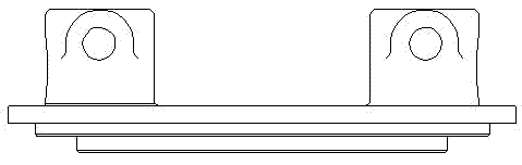
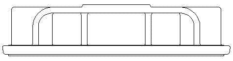
[0002] like figure 1 , 2 As shown, the structure of the traditional butterfly plate is generally truss type or flat plate type. The cross-sectional geometry of these two structures is different, and the deformation of the butterfly plate when it is stressed is large, which affects the sealing effect of the valve.
Method used
View moreImage
Smart ImageViewing Examples

Examples
Embodiment Construction
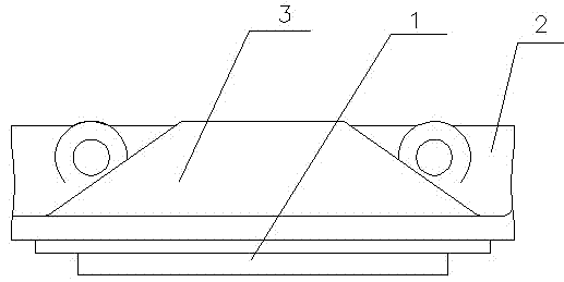
[0009] Such as image 3 As shown, the present invention includes a valve disc 1 and a valve shaft seat 2 for penetrating the valve shaft, the valve shaft seat 2 is fixed on one side of the valve disc 1, and the valve disc 1 on the side where the valve shaft seat 2 is fixed is connected with The conical frustum member 3, the large circular surface of the conical frustum member 3 is integrally connected with the valve flap 1.
Login to View More PUM
 Abstract
The invention relates to a butterfly plate of a butterfly valve, and relates to the field of valve manufacturing. The butterfly plate comprises a valve clack and a valve shaft base used for penetrating through a valve shaft, wherein the valve shaft base is fixed on one side of the valve clack; and the butterfly valve is characterized in that the valve clack fixed on one side of the valve shaft base is connected with a cone round table constructional element, and a large circle surface of the cone round table constructional element is connected with the valve clack in an integral manner. According to the invention, each section is an equal geometric shape, therefore, the butterfly plate is of a constant strength design, the stress of each part is identical, the irregular distortion is small when the butterfly plate is in a temperature variation condition, and the butterfly plate has a good sealing effect when the valve is in a low temperature condition.
Description
technical field [0001] The invention relates to the field of valve manufacturing, in particular to a butterfly plate of a butterfly valve. Background technique [0002] Such as figure 1 , 2 As shown, the structure of the traditional butterfly plate is generally truss type or flat plate type. The cross-sectional geometry of these two structures is different, and the deformation of the butterfly plate when the force is applied is large, which affects the sealing effect of the valve. Contents of the invention [0003] The object of the present invention is to provide a butterfly plate of a butterfly valve with uniform stress and good deformation resistance. [0004] The technical solution to achieve the above purpose is: a butterfly plate of a butterfly valve, including a valve disc and a valve shaft seat for penetrating the valve shaft, the valve shaft seat is fixed on one side of the valve disc, and is characterized in that: the valve shaft seat A conical frustum member ...
Claims
Login to View More Application Information
Patent Timeline
 Patent Type & AuthorityApplications(China)
IPC IPC(8): F16K1/36F16K1/226
Inventor李相臣何余
Owner扬州罗克特种阀门有限公司