railway crane

A technology of machinery and traveling mechanism, applied in the field of railway cranes

Inactive Publication Date: 2016-08-17
KIROW ARDELT GMBH
View PDF7 Cites 0 Cited by
  • Summary
  • Abstract
  • Description
  • Claims
  • Application Information

AI Technical Summary

Problems solved by technology

[0004] When developing such railway cranes, which are especially designed for extremely heavy loads, there were issues of track loading and turnability

Method used


Image

  • railway crane
  • railway crane
  • railway crane

Examples


Embodiment Construction

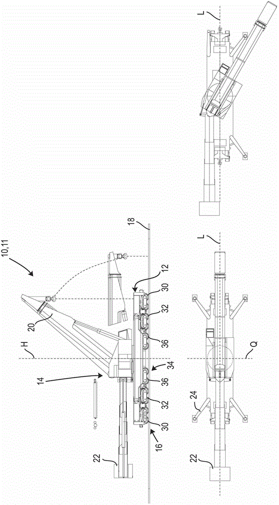
[0031] exist figure 1 A rail vehicle is schematically shown in and marked with 10 . In the following embodiment, the rail vehicle 10 is a railway crane 11 . However, it should be pointed out that the invention can be used not only in railway cranes, but also in other rail vehicles.

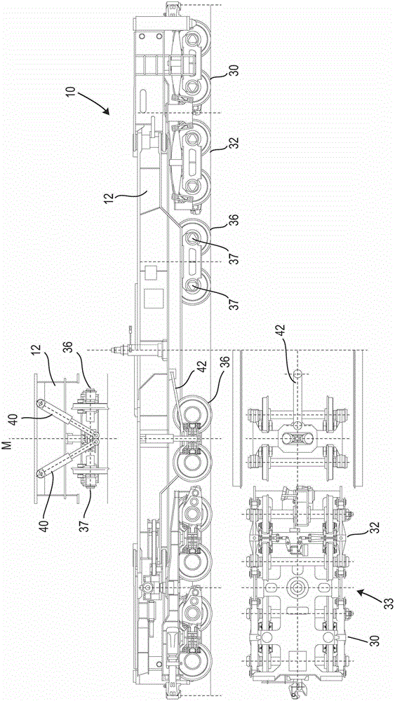
[0032] The basic structure of such a railway crane 11 is known per se from the prior art and therefore needs only a brief description. The railway crane 11 basically consists of a lower car 12 and an upper car 14 . Get off car 12 can move on track 18 by chassis 16. The upper carriage 14 is pivotably mounted on the lower carriage 12 via an axis H that is vertical and directed perpendicularly to the lower carriage 12 . A boom 20 is articulated on the upper carriage 14 , which extends parallel to the longitudinal direction L of the upper carriage 14 . The boom 20 is telescopic in its longitudinal direction and about the axis y with respect to the upper carriage 14 * Arranged in a pivotable mann...


PUM


Abstract

The rail vehicle (10) has drive unit (30) provided at two longitudinal ends of undercarriage (12). A hydraulic cylinder unit (40) is connected with central drive and undercarriage, so that hydraulic cylinder units are supported by the central drive in vertical direction. A hydraulic pump is provided in hydraulic cylinder units.

Description

technical field [0001] The invention relates to a rail vehicle, in particular for accommodating a crane, in particular a railway crane, having an undercarriage which is supported at both longitudinal ends thereof by a chassis unit having at least one axle. In this case, the chassis can be connected to the undercarriage fixedly or at least rotatably about an axis and / or displaceably. Background technique [0002] Rail vehicles of the aforementioned type, in particular for accommodating cranes, also known as railway cranes, are well known. Such a railway crane is known, for example, from publication DE 4237948C2. A railway crane is also known from publication DE 10 2005 027 596 A1. [0003] The basic structure of such a rail vehicle has a chassis supporting the lower vehicle. The chassis comprises at least two chassis units which each have at least one axle. The running gear unit is mechanically connected with the alighting vehicle in a form-fitting manner. In certain cas...

Claims


Application Information

Patent Timeline
Patent Type & Authority Patents(China)
IPC IPC(8): B61D15/00B66C23/50B66C23/62
CPCB61D15/02B61F3/10B61F5/36
Inventor 沃尔特·克尔纳克劳斯·温特西格克里斯蒂安·弗莱克托马斯·恩德莱因托马斯·鲍姆路德维希·克内
Owner KIROW ARDELT GMBH
Why Eureka
Try Eureka