Vehicle body structure

A car body structure and door technology, applied to the upper structure, upper structure sub-assembly, vehicle parts, etc., can solve the problem of increasing the number of parts, making it difficult to give the seat belt reinforcement 4 rigidity, and the outer panel 3 tensile rigidity is easy to decrease and other problems, to achieve the effect of improving tensile rigidity, improving installation rigidity, and improving rigidity

Inactive Publication Date: 2007-12-19
MITSUBISHI MOTORS CORP +1
View PDF7 Cites 0 Cited by
  • Summary
  • Abstract
  • Description
  • Claims
  • Application Information

AI Technical Summary

Problems solved by technology

[0003] However, since the seat belt reinforcement 4 and the stopper reinforcement 7 are substantially perpendicular to the mounting surface of the rear pillar 1, the two reinforcements 4 and 7 are formed separately, and the seat belt reinforcement 4 is relatively small, thereby , there is such a problem that it is generally difficult to impart sufficient rigidity to the seat belt reinforcement 4 and results in an increase in the number of parts
[0004] In addition, when the width of the rear pillar 1 in the roughly vehicle front-rear direction is relatively large, since the outer panel 3 has a relatively large flat surface, there is a disadvantage that the tensile rigidity of the outer panel 3 is likely to decrease.

Method used


Image

  • Vehicle body structure
  • Vehicle body structure
  • Vehicle body structure

Examples


Embodiment

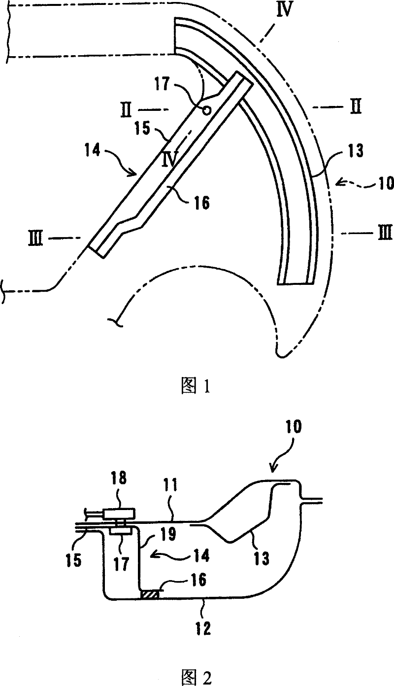
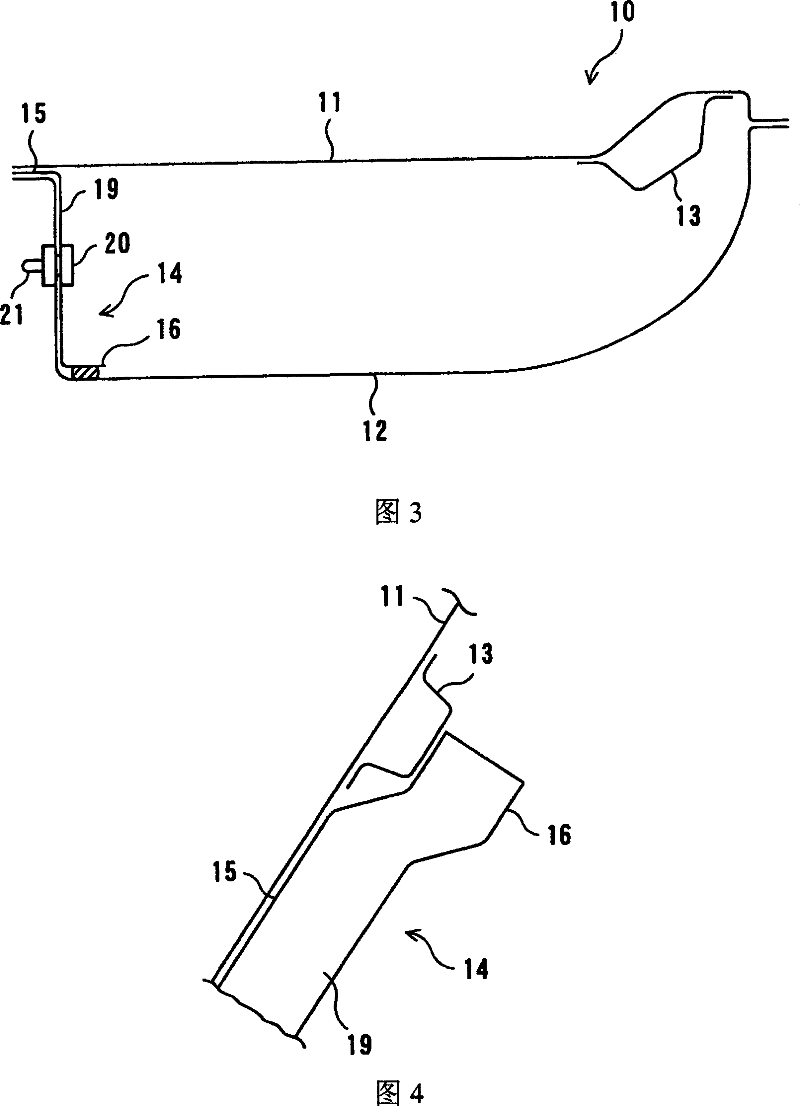
[0027] In FIGS. 1 to 4 , the left and right rear pillars 10 of the vehicle are respectively welded to the edges (Japanese: フランジ) of the inner panel 11 and the outer panel 12 to form a closed section. The rear pillar reinforcement 13 extending in the vertical direction.

[0028] The reinforcement member 14 has a substantially Z-shaped cross-section formed by the vehicle front side edge portion 15, the vehicle rear side edge portion 16, and the middle portion 19 connecting the two edge portions 15, 16 in the substantially vehicle width direction, so as to extend along the rear pillar 10. The vehicle front side end edge extends downward in the vehicle front direction, and is arranged in the rear pillar 10 obliquely relative to the vertical direction, and the vehicle front side edge portion 15 is sandwiched between the two edge portions of the inner panel 11 and the outer panel 12. On the other hand, the vehicle rear side edge portion 16 is joined to the inner surface of the outer...


PUM


Abstract

A reinforcement 14 having approximately a Z-section is installed aslant along the vehicle front side edge of a rear pillar 10 and is secured thereto 10, and the seat belt anchor is attached to the over-part of the reinforcement 14, while the door striker is installed in the lower part of the reinforcement 14, whose top is coupled with the upper part of a rear pillar reinforcement 13. To easily heighten the mounting rigidity of a seat belt anchor and a door striker in the vehicle body rear.

Description

technical field [0001] The present invention relates to a vehicle body structure associated with installation of a seat belt anchor and a retainer, and more particularly to a vehicle body structure suitably applied to a vehicle body rear structure. Background technique [0002] As shown in FIGS. 5 to 7 , in conventional vehicles, the seat belt reinforcement 4 whose end portion is sandwiched between the inner panel 2 and the outer panel 3 on the upper part of the rear pillar 1 is arranged along the inner surface of the inner panel 2 , and is The nut 5 etc. fixed on the seat belt reinforcement 4 supports the seat belt anchor 6 on the rear pillar 1, and on the other hand, a stopper is welded to the vehicle front side inner surface of the lower outer panel 3 of the rear pillar 1. The reinforcement 7 supports the door stop 9 on the rear pillar 1 by means of nuts 8 or the like fixed to the stop reinforcement 7 . [0003] However, since the seat belt reinforcement 4 and the stoppe...

Claims


Application Information

Patent Timeline
Patent Type & Authority Patents(China)
IPC IPC(8): B60R22/24B62D25/00B62D25/04
CPCB62D25/04B60R22/24
Inventor 内田隆信兼原秀夫榊原春彦
Owner MITSUBISHI MOTORS CORP
Why Eureka
Try Eureka