

Vehicle lateral rod mounting apparatus
A technology for mounting devices and vehicles, which is applied to vehicle components, transportation and packaging, and cantilevers mounted on pivots, etc., which can solve the problems of short fixed installation length and inability to obtain rigidity
- Summary
- Abstract
- Description
- Claims
- Application Information
AI Technical Summary
Problems solved by technology
Method used
Image

Examples
Embodiment Construction
[0038] Embodiments of the present invention will be described below in conjunction with the accompanying drawings. Figure 1-14 Embodiments of the present invention are shown. exist Figure 13 and 14 Among them, reference numeral 2 denotes a vehicle, and 4-1 and 4-2 denote two frames on the left and right sides of the vehicle 2.
[0039] The rear of the vehicle 2 has rear axle shafts 6-1 and 6-2, the inner ends of which are connected to a rear differential (not shown) located below and between the vehicle frames 4-1 and 4-2, and the outer end is positioned at the side of vehicle 2, wheel hub 8-1 and 8-2 are respectively arranged on the outer end of rear axle shaft 6-1 and 6-2, and rear wheel 10-1 and 10-2 are contained in wheel hub 8-1 and 8 respectively. -2 on.
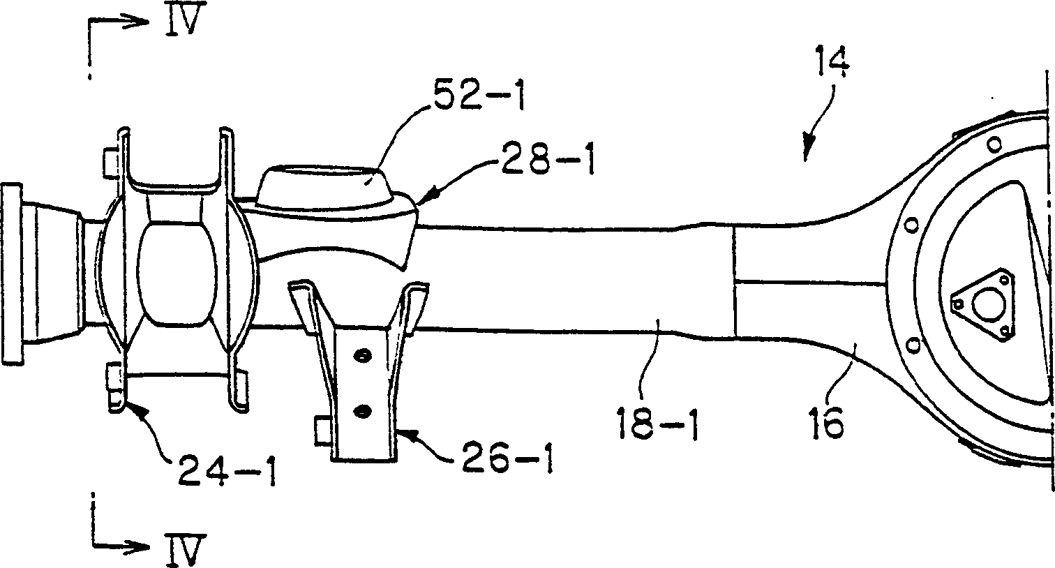
[0040] The vehicle 2 has an axle arrangement 12 between the vehicle frames 4-1 and 4-2 for supporting the rear wheels 10-1 and 10-2. The axle unit 12 includes an axle housing 14 extending in the transverse direc...
PUM
 Abstract
Description
Claims
Application Information