Power unit device and power converter device

a technology of power unit and power converter, which is applied in the direction of lighting and heating apparatus, electrical apparatus casings/cabinets/drawers, instruments, etc., to achieve excellent manufacturing aspects and increase layout freedom

Active Publication Date: 2008-02-19
MITSUBISHI ELECTRIC CORP
View PDF11 Cites 11 Cited by
  • Summary
  • Abstract
  • Description
  • Claims
  • Application Information

AI Technical Summary

Benefits of technology

[0009]In this invention, because a power module, containing power semiconductor elements for one phase, and a smoothing condenser are both mounted on a first heat-receiving face and a second heat-receiving face of a heat sink and fixed in the form of a stack by fixing means, the power unit device obtained can be made small, and special measures of plant and labor at the time of assembly are unnecessary. And, the content of existing electrical equipment assembly plant and so on can also be observed, and universality in the manufacturing aspect is excellent.
[0010]And, when an efficient multi-phase motor such as an ordinary 3-phase motor is to be controlled, multiple power unit devices can be provided in correspondence with the number of phases required, they can be disposed in conformity with the available space, and the freedom of layout increases. Also, by a heat sink being in firm contact individually with each of the power modules, which are sources of heat production, the cooling effect can be made uniform among phases, and by the power unit devices being disposed with a uniform angular spacing or uniform straight-line spacing, the occurrence of surge voltages can also be made uniform among phases.

Problems solved by technology

In this related art, because multiple power modules are mounted on a single heat sink, the heat sink becomes large, and compared to the relatively small power modules and peripheral constituent members the heat sink becomes excessive in size and weight, at the time of assembly just because of the heat sink the production line becomes long and non-standard special measures become necessary like having to strengthen its load-bearing capacity, and there has been the issue that in electrical equipment manufacturing sites where space restrictions are severe and the object is light work this can become a problem.

Method used


Image

  • Power unit device and power converter device
  • Power unit device and power converter device
  • Power unit device and power converter device

Examples


first preferred embodiment

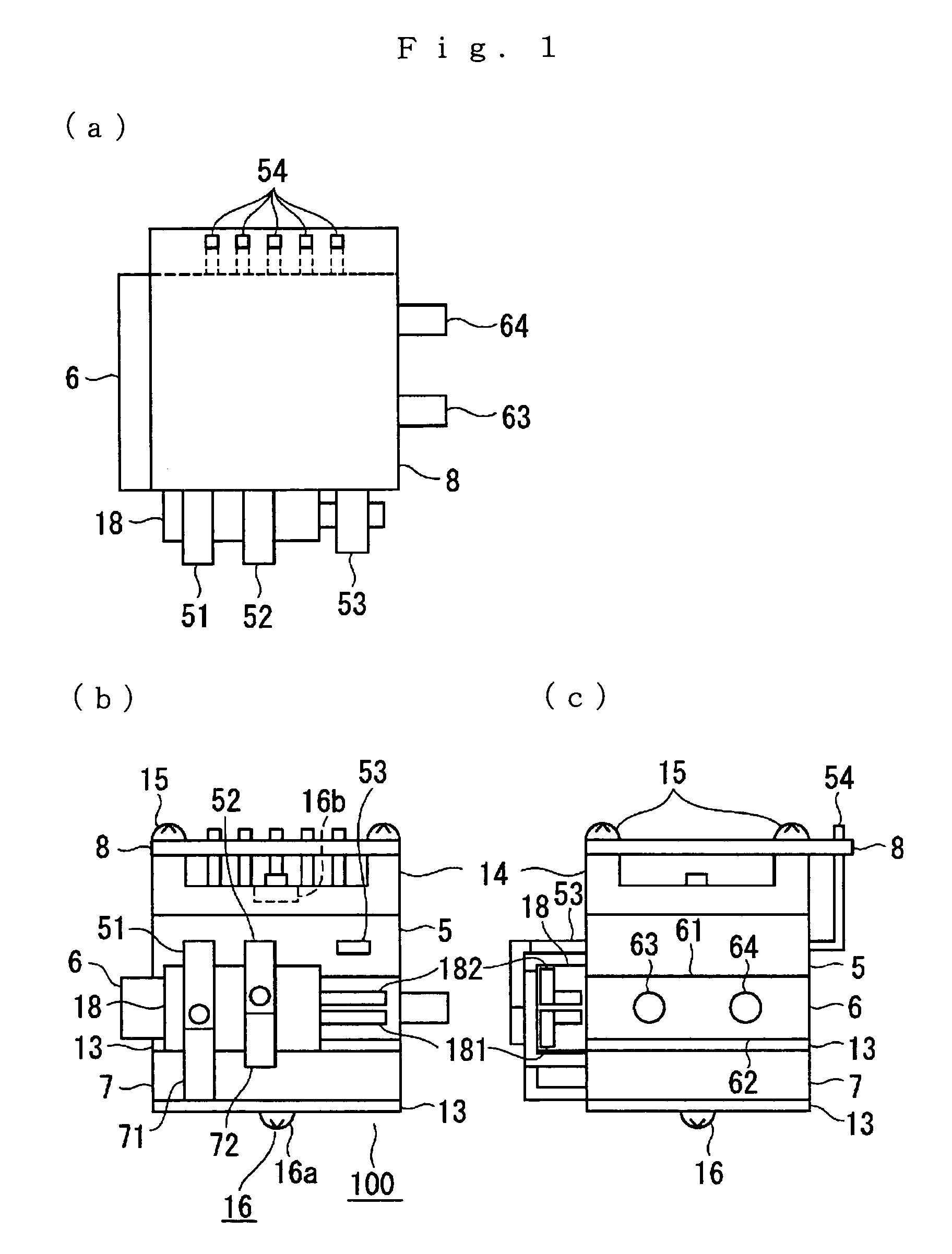
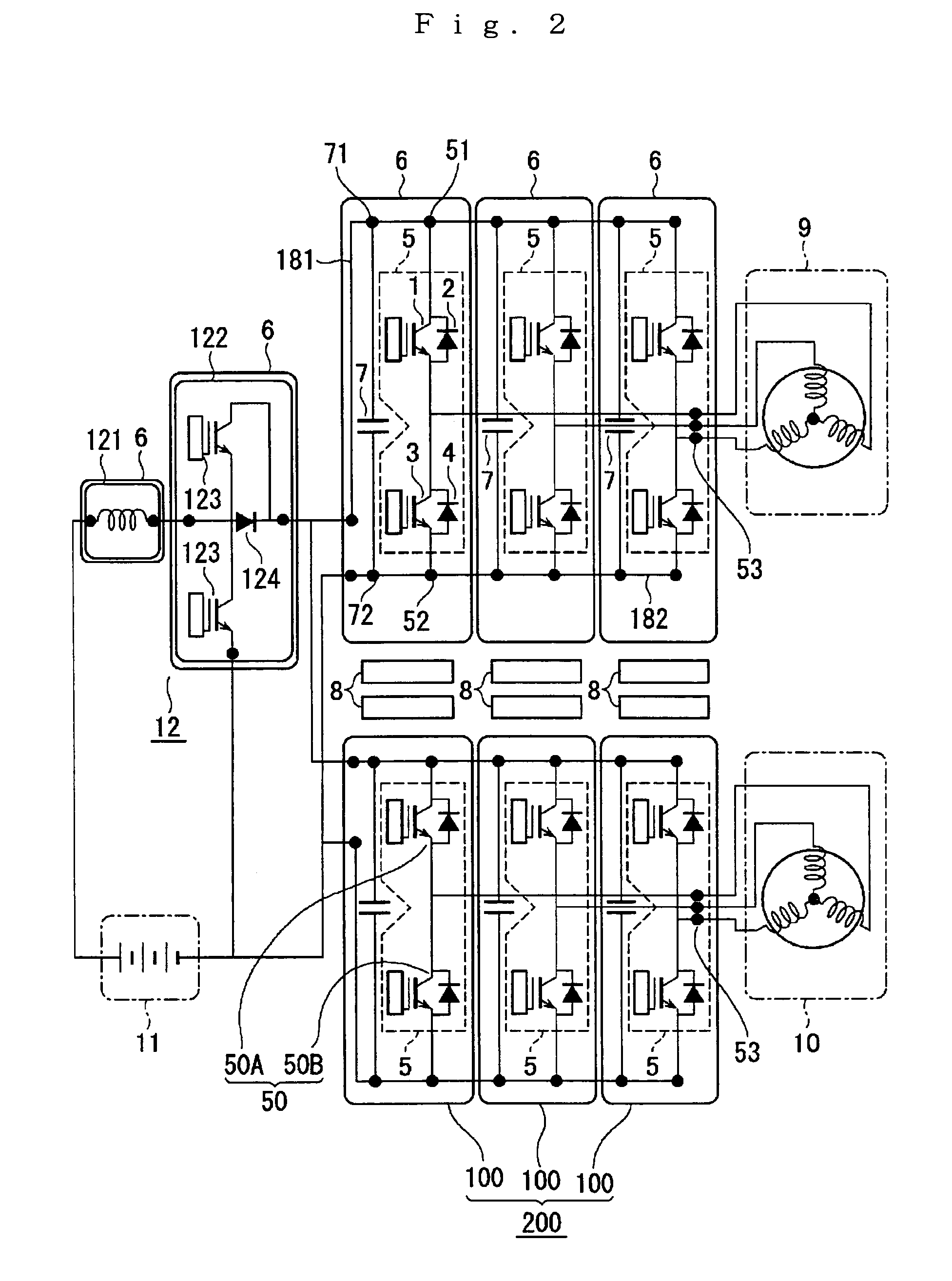
[0015]FIG. 1 shows schematically the exterior of a power unit device according to a first preferred embodiment of the invention, FIG. 1A being a plan view, FIG. 1B a front view and FIG. 1C a side view. FIG. 2 is a schematic system view showing the internal construction of the power unit device shown in FIGS. 1A through 1C and a power converter device constructed to control a 3-phase a.c. rotary electric machine (hereinafter simply called a motor) using six of these power unit devices. The same reference numerals denote the same or equivalent parts throughout the figures.

[0016]In the figures, a power unit device 100 has a heat sink 6 having a first heat-receiving part 61 and formed on the opposite side from that a second heat-receiving part 62; a power module 5, in firm contact with the first heat-receiving part 61, containing a power semiconductor element 50 for performing DC-AC conversion (during power operation) and AC-DC conversion (during regenerative operation) for one phase; a...

second preferred embodiment

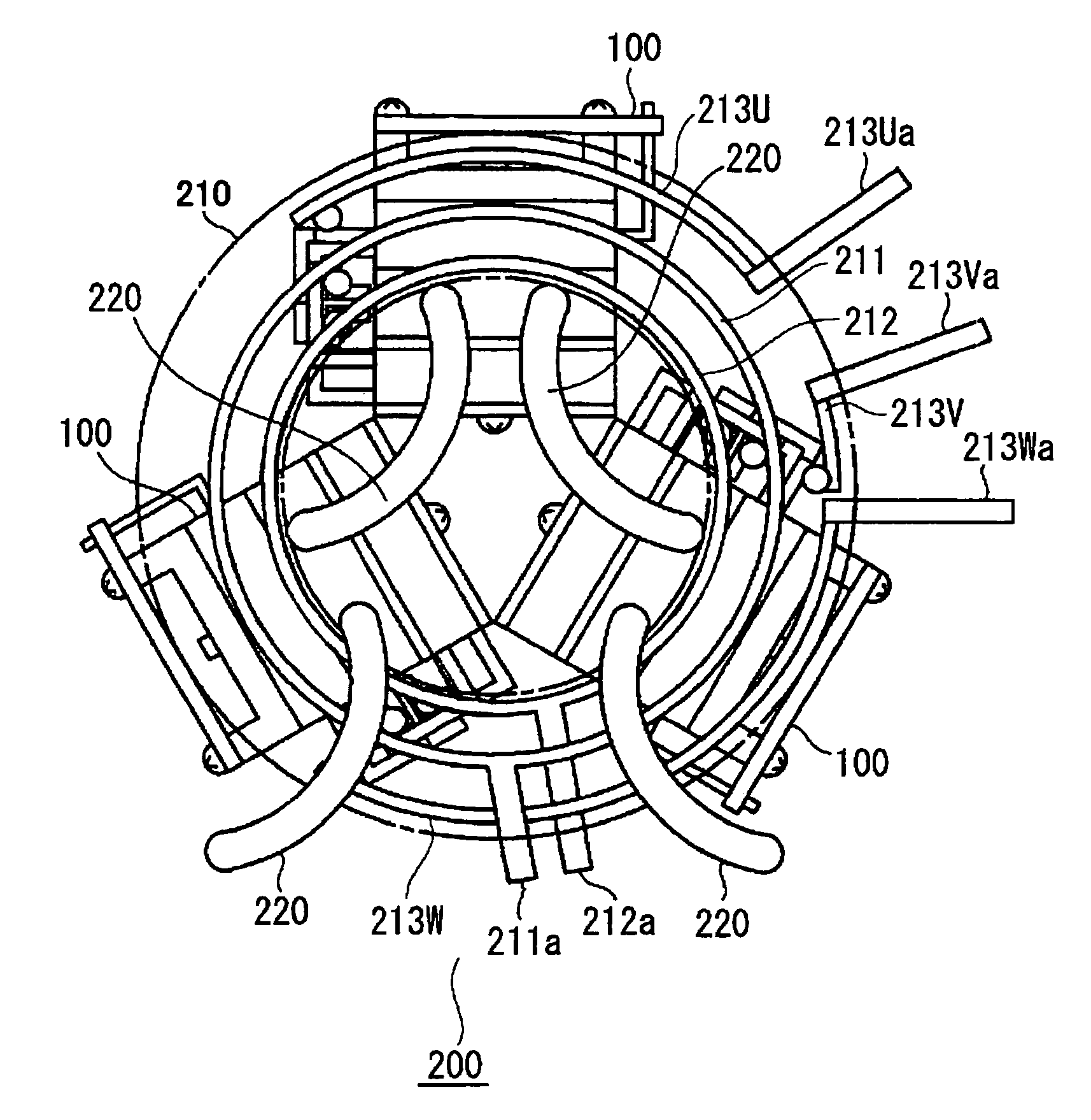
[0029]FIG. 3 is a construction view showing schematically the main parts of a power converter device according to a second preferred embodiment of the invention. In this second preferred embodiment, three one-phase power unit devices 100 according to the first preferred embodiment shown in FIG. 1 are used to construct a power converter device for drive-controlling one 3-phase motor. In the figure, a power converter device 200 has three power unit devices 100 disposed radially with approximately uniform angular spacing, circular conductors 211, 212 are connected to conducting members (181, 182 in FIG. 1) of the power unit devices 100 by screw fastenings (not shown), and terminal parts 211a, 212a of the conductors 211, 212 are connected to the P pole and the N pole of a power supply battery (not shown).

[0030]Main terminal connection parts (53 of FIG. 1) for conducting power between the power unit devices 100 and the motor side are also connected to circular conductors 213U, 213V, 213W...

third preferred embodiment

[0032]FIG. 4 is a construction view showing schematically the main parts of a power converter device according to a third preferred embodiment of the invention. Whereas in the power converter device of the second preferred embodiment described above three of the power unit device shown in FIG. 1 were disposed in a circle with uniform angular spacing, in this third preferred embodiment three are disposed in a straight line. In the figure, the power unit devices 100 are disposed with approximately equal spacing in a straight line, and straight conductors 211, 212 of a P pole and an N pole connected to a power supply battery are connected to the conducting members of the power unit devices 100 (181, 182 in FIG. 1) by screw fastenings (not shown). The main terminal connection parts (53 of FIG. 1) for conducting power to the motor side of the power modules are also integrally embedded in a power conductor member 210 and connected by screw fastenings, and electrically connected to the mot...


PUM


Abstract

A power unit device which can be made small, with which special measures of plant and labor at the time of assembly are unnecessary, and of which assembly is easy and universality in its manufacturing aspect is excellent. The power unit device has a heat sink having a first heat-receiving part and formed on the opposite side from this a second heat-receiving part; a power module, in firm contact with the first heat-receiving part, containing a power semiconductor element for performing DC-AC conversion and / or AC-DC conversion for one phase; a smoothing condenser, in firm contact with the second heat-receiving part, for suppressing ripple current of the power semiconductor element; and fixing means passing through the power module, the heat sink and the smoothing condenser.

Description

BACKGROUND OF THE INVENTION[0001]1. Field of the Invention[0002]This invention relates to a power unit device and a power converter device that can be suitably used for example as control devices of an AC motor mounted in a fuel cell car or a hybrid car.[0003]2. Description of the Related Art[0004]An inverter device for drive-controlling a motor in for example a hybrid vehicle using both an internal combustion engine and batteries or an electric vehicle using a DC power source such as batteries or fuel cells has as main constituent parts a power semiconductor element for converting power, a circuit board for controlling this, and a smoothing condenser and a heat sink, and technology is known wherein to make an assembly of these parts compact a number of power modules each containing inside it a power semiconductor element for converting power are disposed on a face orthogonal to a motor axis and this face is made a heat sink for dissipating heat produced by the power module and ther...

Claims


Application Information

Patent Timeline
Patent Type & Authority Patents(United States)
IPC IPC(8): H05K7/20
CPCH05K7/20927B60K2001/003
Inventor YAMABUCHI, HIROSHIKURAMOTO, YUJIKIMURA, TORU
Owner MITSUBISHI ELECTRIC CORP
Why Eureka
Try Eureka