Brake apparatus

a technology for brakes and components, applied in brake systems, vehicle components, transportation and packaging, etc., can solve problems such as the upsizing of the whole housing of the brake apparatus, and achieve the effect of enhancing the freedom of layou

Inactive Publication Date: 2012-06-07
HITACHI AUTOMOTIVE SYST LTD
View PDF5 Cites 11 Cited by
  • Summary
  • Abstract
  • Description
  • Claims
  • Application Information

AI Technical Summary

Benefits of technology

[0037]The present invention can provide a brake apparatus capable of enhancing a freedom of layout of a rotary gear pump and serving for a compact housing.

Problems solved by technology

This leads to upsizing of a whole housing of the brake apparatus.

Method used


Image

  • Brake apparatus
  • Brake apparatus
  • Brake apparatus

Examples


Embodiment Construction

[0045]Referring to FIG. 1 to FIG. 7, a brake apparatus according to an embodiment of the present invention will be explained hereinafter.

[0046][Construction of Hydraulic Circuit of Hydraulic Brake Control System]

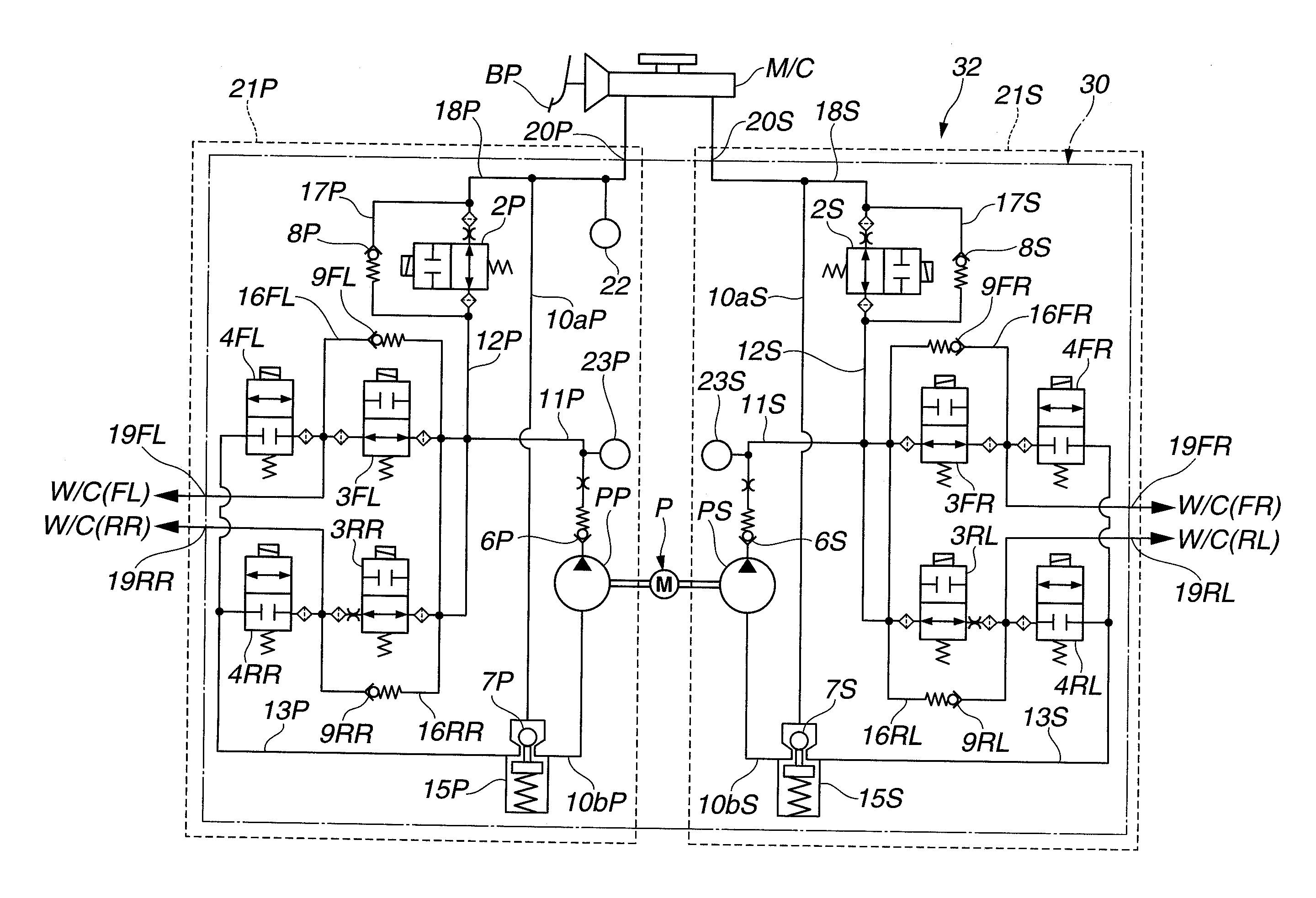
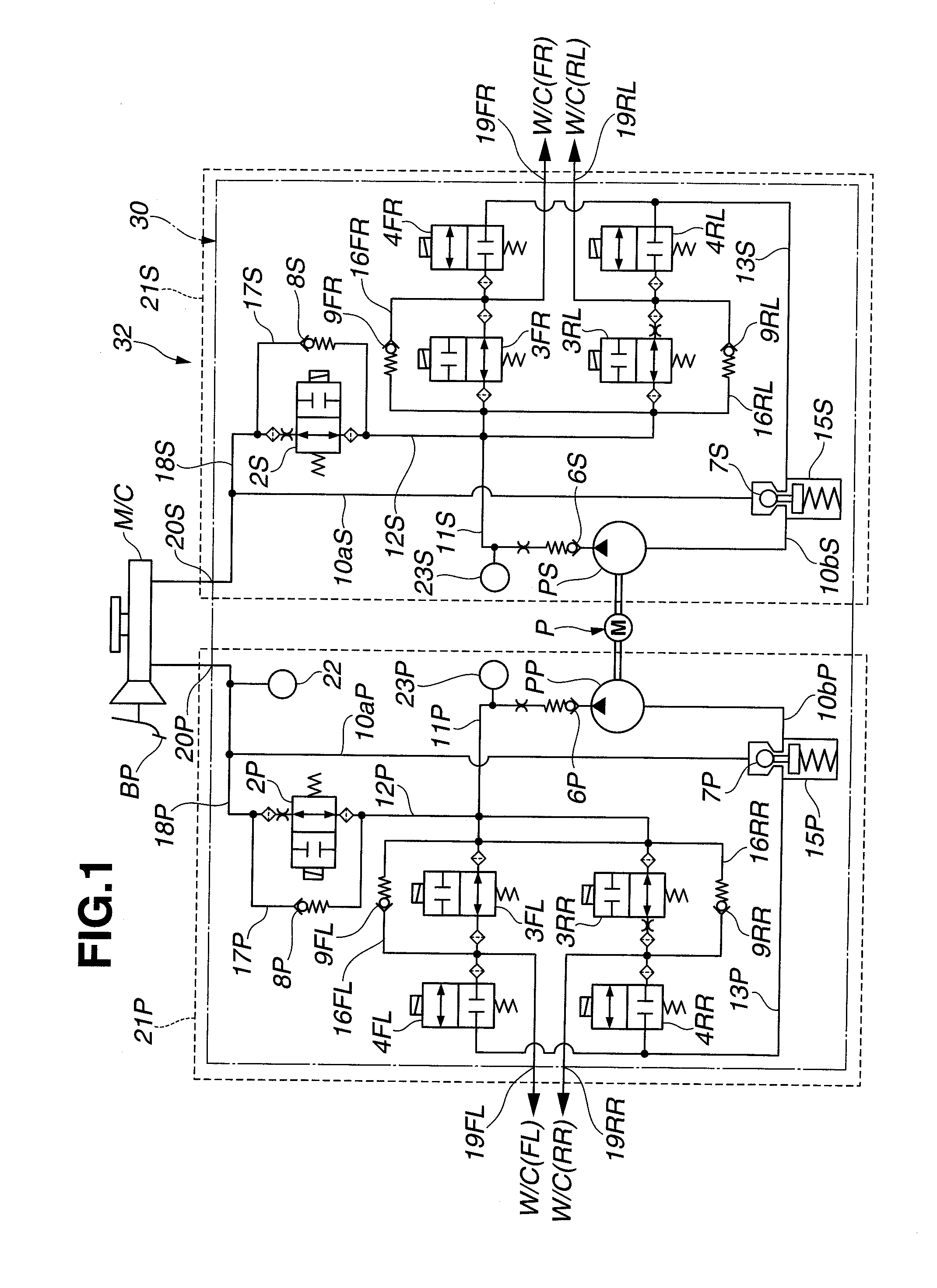
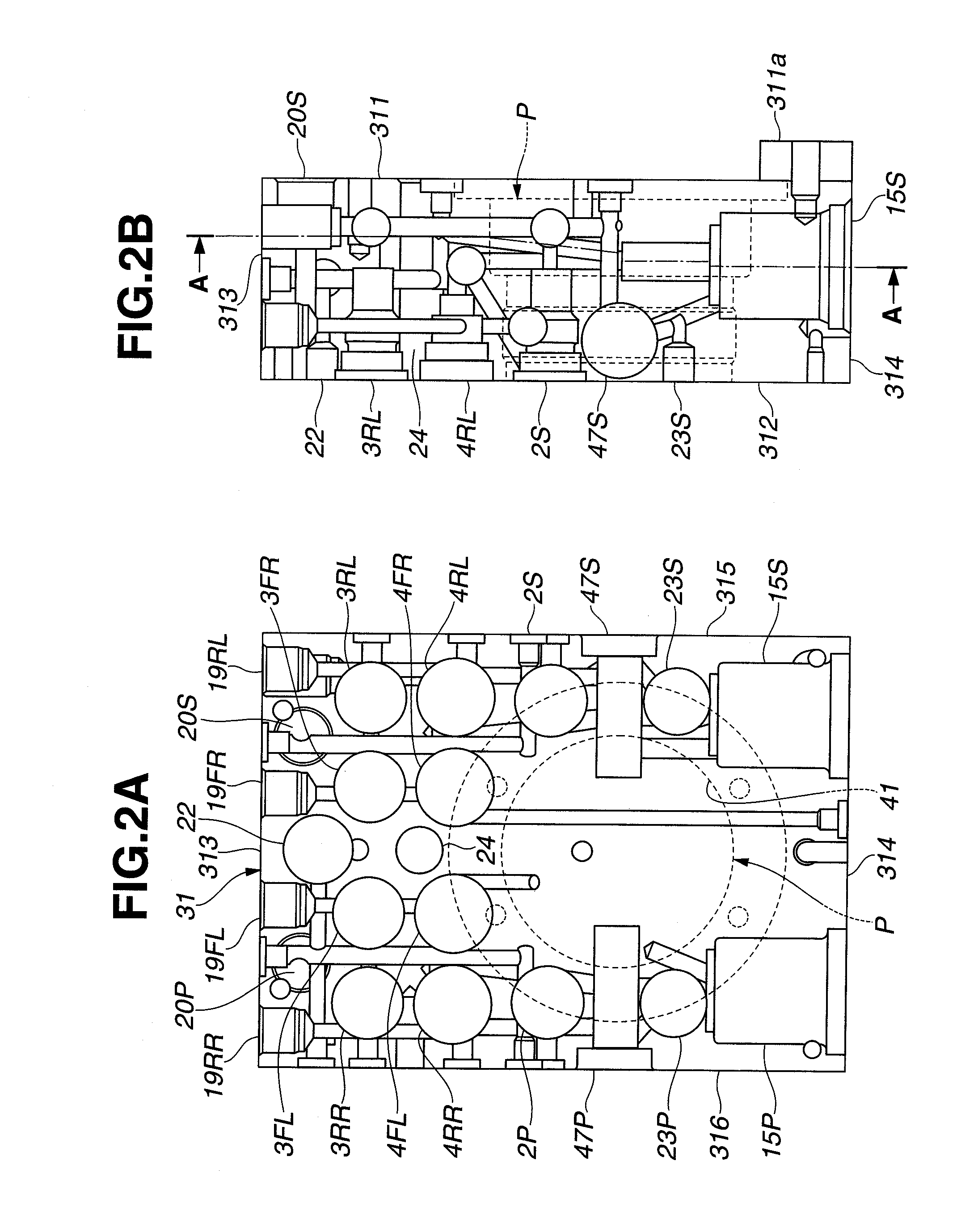
[0047]FIG. 1 is a hydraulic circuit diagram of hydraulic brake control system 32 according to an embodiment of the present invention. As shown in FIG. 1, the hydraulic circuit is formed in hydraulic control unit 30 disposed between master cylinder M / C and wheel cylinder W / C. Hydraulic control unit 30 includes generally rectangular solid-shaped housing 31 cut out from an aluminum block, and a plurality of fluid passages formed in housing 31, pump unit P, motor M, and a plurality of valves as explained below.

[0048]Hydraulic brake control system 32 performs hydraulic control in accordance with the hydraulic pressure requested in vehicle dynamics control (VDC) and anti-lock brake system (ABS) control by a controller. Hydraulic brake control system 32 has a so-called X piping con...


PUM


Abstract

A brake apparatus including a housing, a piston body disposed within each of a pair of closed-ended bores formed in the housing, a first elastic member that biases the piston body toward a closed end of the respective bores, a fluid passage opened to the closed end of the respective bores, a pressure regulating valve disposed in the fluid passage, and a rotary gear pump disposed in a region between the pressure regulating valve disposed in the fluid passage opened to the closed end of one of the bores and the pressure regulating valve disposed in the fluid passage opened to the closed end of the other of the bores. The fluid passages are formed to be offset from respective central axes of the piston bodies in such a direction that the fluid passages are spaced apart from each other.

Description

BACKGROUND OF THE INVENTION[0001]The present invention relates to a brake apparatus that has a reservoir function of reserving a brake fluid.[0002]Japanese Patent No. 3937554 discloses a brake apparatus usable in an anti-lock brake system (ABS), etc., in which a piston for a reservoir and a pressure regulating valve disposed above the piston are arranged such that central axes thereof are aligned with each other.SUMMARY OF THE INVENTION[0003]However, in the above-described conventional art, the pressure regulating valve is constituted of multiple parts and has an axial length elongated for stroke in an axial direction thereof. Therefore, it is required to arrange a reservoir to be spaced from a pump part disposed in the vicinity of the reservoir in order to avoid interference therebetween. This leads to upsizing of a whole housing of the brake apparatus.[0004]It is an object of the present invention to provide a brake apparatus serving for a compact housing thereof.[0005]The other o...

Claims


Application Information

Patent Timeline
Patent Type & Authority Applications(United States)
IPC IPC(8): B60T13/16
CPCB60T8/368B60T8/4872B60T13/686B60T13/662B60T13/145
Inventor TERASHIMA, KAZUYANUMAKURA, KOJITSURUOKA, KATSUMA
Owner HITACHI AUTOMOTIVE SYST LTD
Why Eureka
Try Eureka