Pulse transformer

Active Publication Date: 2014-10-02
TDK CORPARATION
View PDF4 Cites 12 Cited by
  • Summary
  • Abstract
  • Description
  • Claims
  • Application Information

AI Technical Summary

Benefits of technology

The invention provides a pulse transformer that can be placed on a printed circuit board without interfering with other components. The design ensures that the transformer can withstand high voltages even when multiple transformers are placed close to each other.

Problems solved by technology

Typically, in a circuit component of such a type, a clearance to be ensured between the primary side and secondary side is prescribed in the specification, so that a layout illustrated in FIG. 11B is likely to fail to satisfy the specification.
In this case, however, a region R1 on the printed circuit board becomes a dead space, decreasing use efficiency of the printed circuit board.
Thus, a routing distance of the wiring patterns on the printed circuit board is disadvantageously increased, and there is a possibility that a difference in characteristics occurs between a signal passing through the pulse transformer 11 and a signal passing through the pulse transformer 12.
In this case, however, a region R2 on the printed circuit board becomes a dead space, decreasing use efficiency of the printed circuit board.
As described above, when a common type pulse transformer having a rectangular shape in a plan view is used, it is difficult to efficiently lay out the plurality of pulse transformers on the printed circuit board while ensuring sufficient withstand voltage between the primary and secondary sides.
Therefore, when the common type pulse transformer is used, freedom of layout on the printed circuit board is restricted.

Method used


Image

  • Pulse transformer
  • Pulse transformer
  • Pulse transformer

Examples


Embodiment Construction

[0048]Preferred embodiments of the present invention will be explained below in detail with reference to the accompanying drawings.

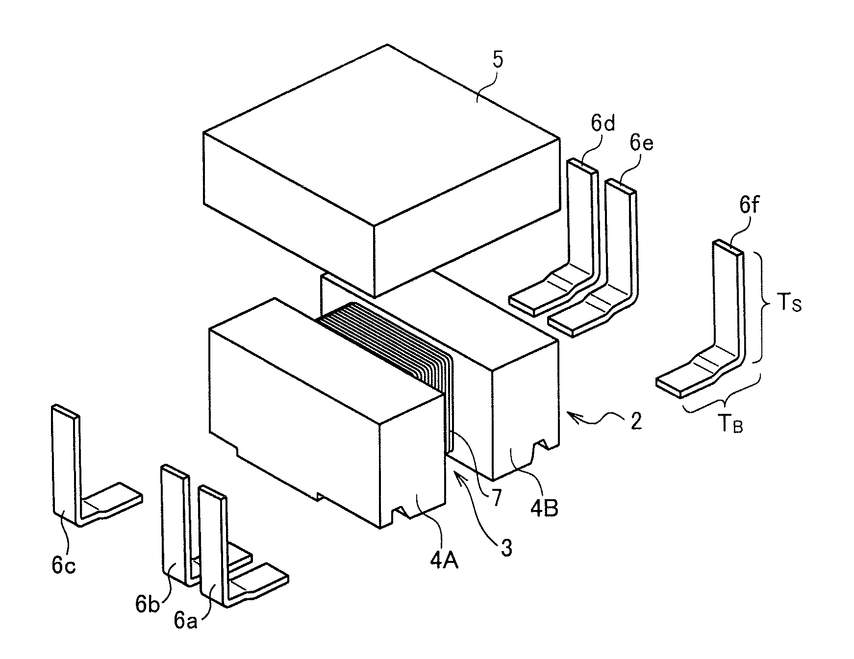
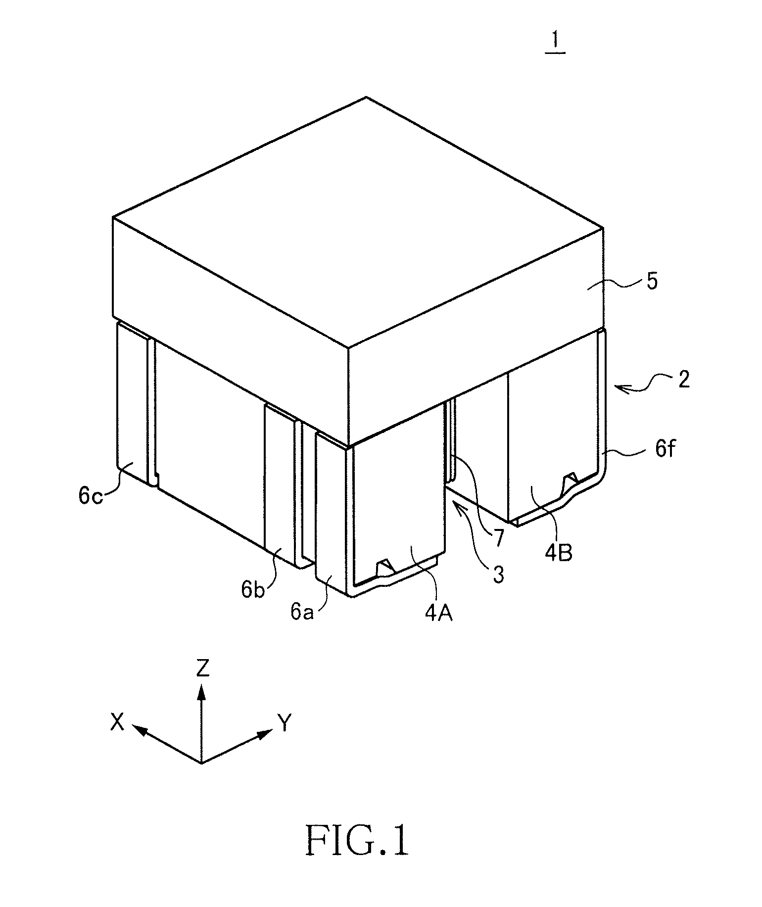
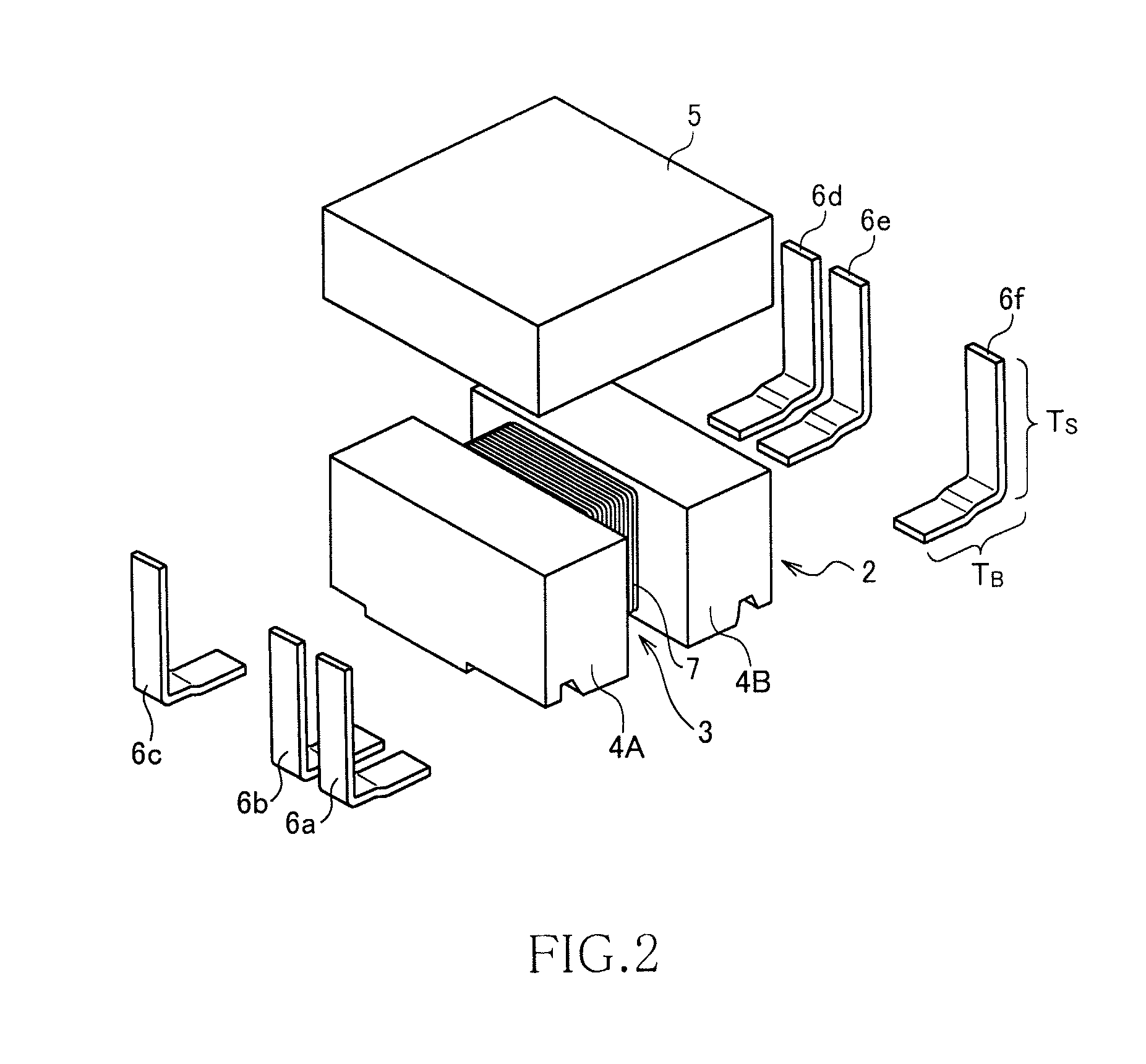
[0049]FIG. 1 is a schematic perspective view illustrating an outer appearance of a pulse transformer 1 according to a preferred embodiment of the present invention. FIG. 2 is an exploded perspective view of the pulse transformer 1 according to the present embodiment, and FIG. 3 is a schematic perspective view of the pulse transformer 1 set with the top and bottom thereof reversed and viewed from the bottom side.

[0050]As illustrated in FIGS. 1 to 3, the pulse transformer 1 according to the present embodiment includes a drum core 2, a plate core 5, six terminal fittings 6a to 6f, and a coil 7 having a wire wound around the drum core 2. Although not especially limited, the pulse transformer 1 has a size of about 3.3 mm (X-direction)×about 3.3 mm (Y-direction)×about 2.7 mm (Z-direction). Thus, a planar shape of the pulse transformer 1 as viewed in the Z-dire...


PUM


Abstract

A pulse transformer 1 is provided with a drum core 2 including a winding core 3 and first and second flanges 4A and 4B, and wires S1 to S4 wound around the winding core 3. Terminal electrodes P1 and N1 and a center tap CT2 are provided on the flange 4A, and terminal electrodes P2 and N2 and a center tap CT1 are provided on the flange 4B. Each end of the wires S1 to S4 is connected to a corresponding one of the terminal electrodes P1 and N1, the center tap CT2, the terminal electrodes P2 and N2, and the center tap CT1. A length of the drum core 2 in X direction is equal to a length of the drum core 2 in Y direction, so that the shape of the mounting region on the printed circuit board is not changed even after being rotated by 90°.

Description

BACKGROUND OF THE INVENTION[0001]1. Field of the Invention[0002]The present invention relates to a pulse transformer and, more particularly, to a surface-mount pulse transformer using a drum-type core.[0003]2. Description of Related Art[0004]In recent years, in a circuit component such as a connecter, a pulse transformer is widely used for isolating a differential signal at an input side (primary side) and a differential signal at an output side (secondary side). In order to mount a plurality of pulse transformers on a printed circuit board at high density, it is preferable to use a surface-mount pulse transformer using a drum core (see Japanese Patent Application Laid-Open Nos. 2009-302321 and 2010-109267).[0005]A pulse transformer described in the Japanese Patent Application Laid-Open No. 2010-109267 has a configuration in which primary-side terminal electrodes and a secondary-side center tap are formed in one flange, and secondary-side terminal electrodes and a primary-side cente...

Claims


Application Information

Patent Timeline
IPC IPC(8): H01F27/29
CPCH01F27/29H01F19/08H01F27/027H01F27/292H01F3/10H01F27/2828
Inventor TAKAGI, NOBUOTSUCHIDA, SETUMIKOGAMI, TASUKU
Owner TDK CORPARATION
Why Eureka
Try Eureka