Engine supporting structure for working vehicle

a technology for working vehicles and supporting structures, which is applied in the direction of electric propulsion mounting, jet propulsion mounting, transportation and packaging, etc., can solve the problems of high production costs, increase in the number of components, and complicated manufacturing processes, so as to improve the bending rigidity of the mounting plate, eliminate the structure, and simplify the manufacturing process

Inactive Publication Date: 2015-03-24
YANMAR POWER TECHNOLOGY CO LTD
View PDF14 Cites 3 Cited by
  • Summary
  • Abstract
  • Description
  • Claims
  • Application Information

AI Technical Summary

Benefits of technology

[0012]The embodiments of the present invention provide the following advantageous effects.
[0013]According to one embodiment of the present invention, the engine supporting structure includes one piece of mount plate to support the plurality of engine mounts. Then, the mount plate may be supported by a stand having a skin-stressed sheet-metal body construction (monocoque construction). Accordingly, the wall surfaces of the stand disperse the stress, so that the bending rigidity of the mount plate can be improved.
[0014]According one embodiment of the present invention, the mount plate supports the engine and the radiator. Accordingly, this eliminates the structure to support the radiator separately, so that the simplification of the manufacturing process and the reduction in costs can be achieved.

Problems solved by technology

Accordingly, there has been a problem in that a welding operation along with jigs is essential, and manufacturing processes are complicated.
Further, there has been a problem in that the number of components increases, and production costs are high.

Method used


Image

  • Engine supporting structure for working vehicle
  • Engine supporting structure for working vehicle
  • Engine supporting structure for working vehicle

Examples


first embodiment

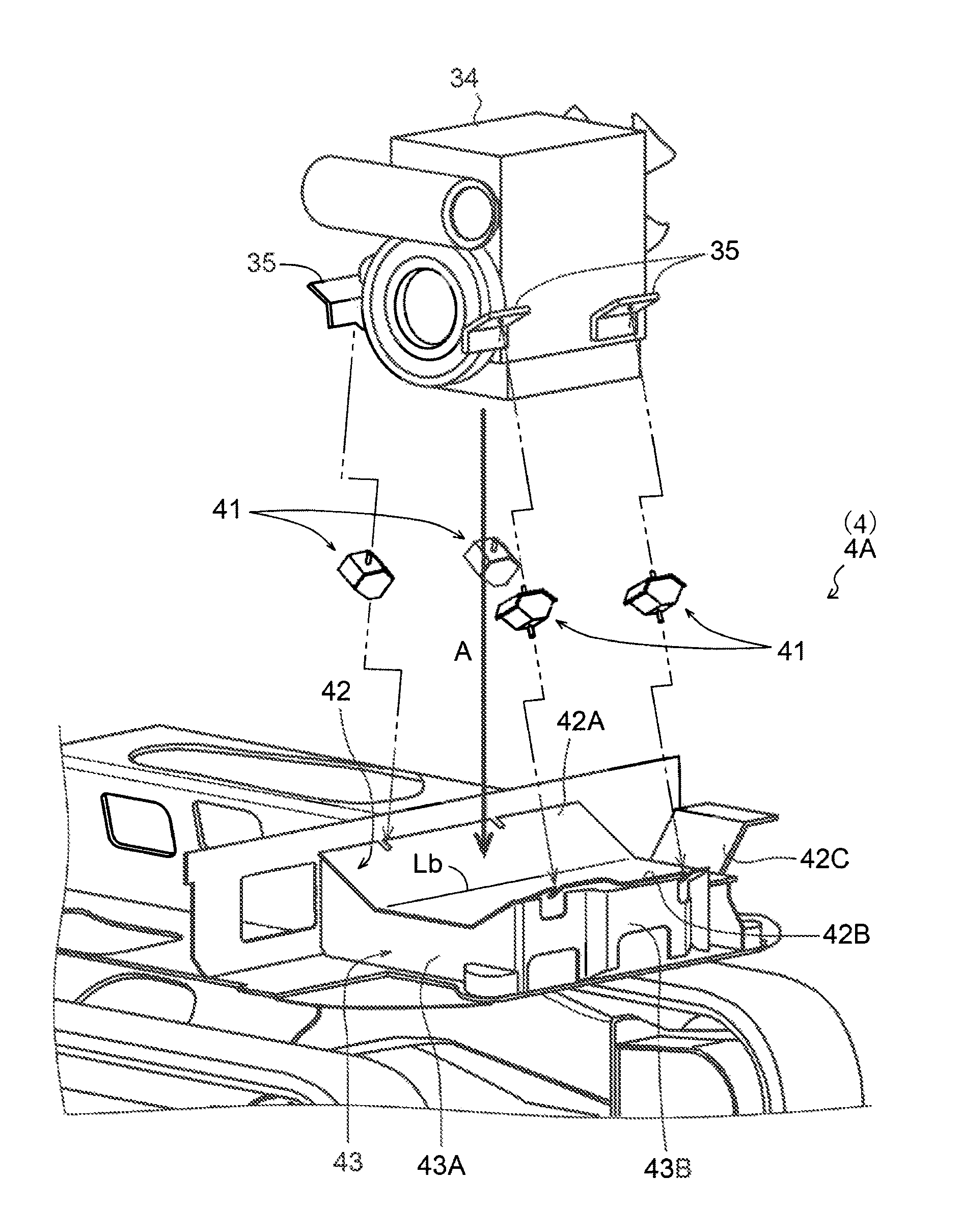
[0034]Hereinafter, the engine supporting structure 4 (hereinafter referred to as “engine supporting structure 4A”) according to the present invention will be described in detail.

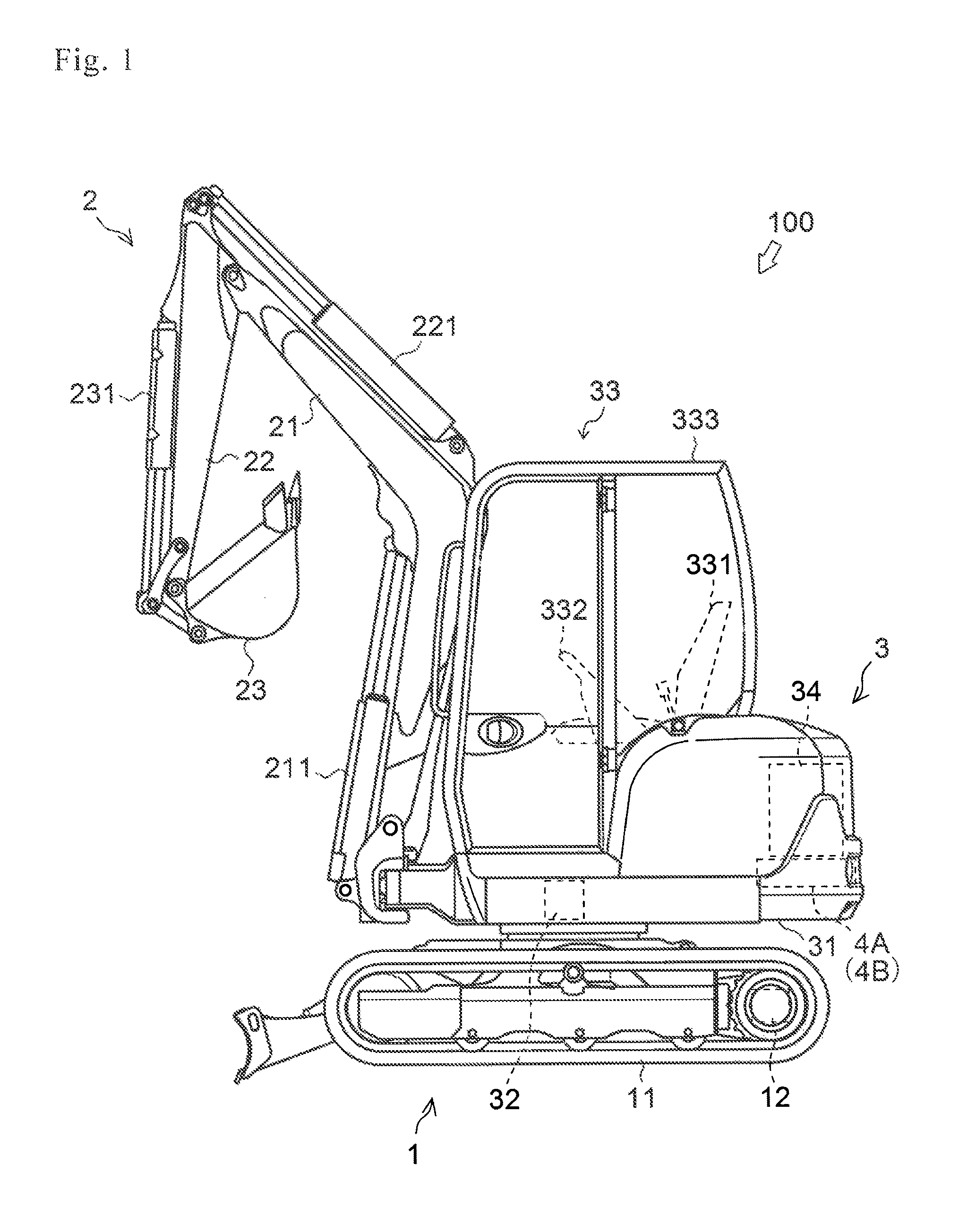
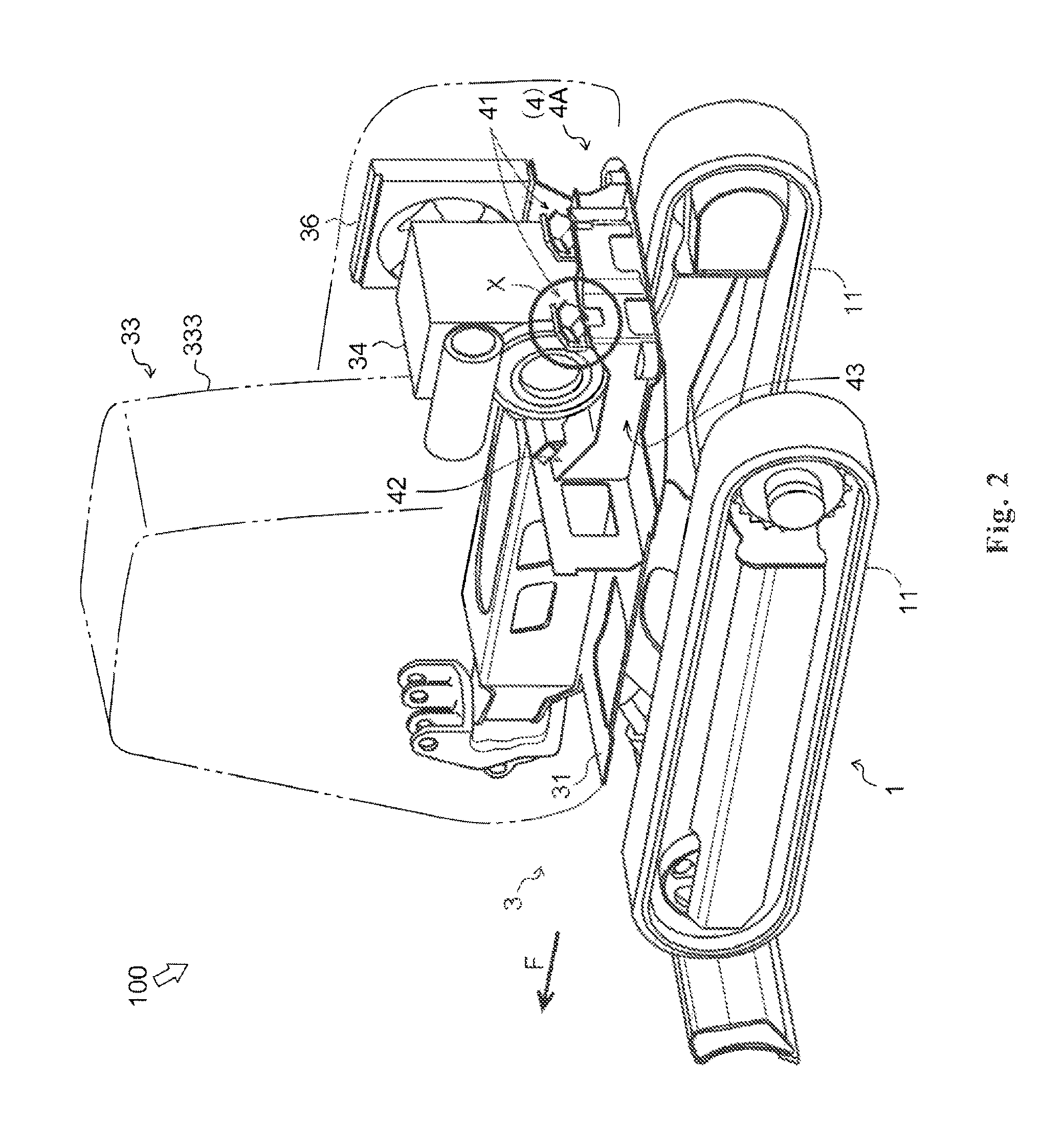
[0035]FIG. 2 is a diagram illustrating the engine supporting structure 4A according to the first embodiment of the present invention. FIG. 3 is an enlarged view of an area X of FIG. 2. Then, FIG. 4 is a diagram illustrating the process of mounting the engine 34. It is noted that an arrow F in FIG. 2 represents the advancing direction of the backhoe 100. Also, an arrow A illustrated FIG. 4 represents a mounting direction when the engine 34 is mounted. Further, a thin line Lb illustrated in FIG. 4 represents a bending line of a mount plate 42.

[0036]As is illustrated in FIG. 2, the engine supporting structure 4A is mainly constituted by an engine mount 41 and the mount plate 42.

[0037]As is illustrated in FIG. 3, the engine mount 41 is constituted by a vibration isolation rubber 41R and attaching bolts 41B. The ...

second embodiment

[0045]Next, an engine supporting structure 4 (hereinafter referred to as “engine supporting structure 4B”) according to the present invention will be described in detail.

[0046]FIG. 5 is a diagram illustrating the engine supporting structure 4B according to the second embodiment of the present invention. FIG. 6 is an enlarged view of an area X of FIG. 5. Then, FIG. 7 is a diagram illustrating the process of mounting the engine 34. It is noted that an arrow F in FIG. 5 represents the advancing direction of the backhoe 100. Also, an arrow A illustrated FIG. 7 represents a mounting direction when the engine 34 is mounted. Further, a thin line Lw illustrated in FIG. 7 represents a welding line of a mount plate 42.

[0047]The engine supporting structure 4B is approximately similar to the engine supporting structure 4A according to the first embodiment of the present invention. Accordingly, the features that are different from those of the engine supporting structure 4A will be described bel...


PUM


Abstract

It is an object of the present invention to provide an engine supporting structure for a working vehicle that can realize the simplification of manufacturing processes and the reduction of costs. With respect to an engine supporting structure for a working vehicle (backhoe) that includes an engine and a plurality of engine mounts to support the engine, the engine supporting structure includes one piece of mount plate to support the plurality of engine mounts, wherein the mount plate is supported by a stand having a skin-stressed sheet-metal body construction, surrounding with beams welded to the left and right end portions of the mount plate, and with beams welded to the anterior and posterior end portions of the mount plate.

Description

CROSS-REFERENCE TO RELATED APPLICATIONS[0001]The present application claims priority to European Patent Application No. 13305471.8, filed on Apr. 11, 2013, the disclosure of which is incorporated herein in its entirety by reference thereto.BACKGROUND OF THE INVENTION[0002]1. Field of the Invention[0003]The present invention relates to a technology of an engine supporting structure for a working vehicle.[0004]2. Background Art[0005]Conventionally, a construction equipment vehicle typified by a backhoe and an agricultural equipment vehicle typified by a tractor have been known. These working vehicles are equipped with an engine and operated by the motive power of the engine. For example, the backhoe travels based on the motive power of the engine and carries out an excavating operation based on the motive power of the engine (for example, see WO2007 / 004327).[0006]Incidentally, the engine of the working vehicle is supported by a plurality of engine mounts. Then, each engine mount is su...

Claims


Application Information

Patent Timeline
Patent Type & Authority Patents(United States)
IPC IPC(8): B60K5/12B60K11/04E02F9/08
CPCB60K5/12E02F9/0866B60K11/04B60Y2200/412
Inventor DRIANT, MATHIEUCABORET, CHRISTOPHE
Owner YANMAR POWER TECHNOLOGY CO LTD
Why Eureka
Try Eureka