Front sub-frame structure

一种前副车架、车身的技术,应用在下部结构、车辆部件、保险杠等方向,能够解决上下方向出现偏移等问题,达到提高支承刚性的效果

Inactive Publication Date: 2018-07-31
MAZDA MOTOR CORP
View PDF7 Cites 3 Cited by
  • Summary
  • Abstract
  • Description
  • Claims
  • Application Information

AI Technical Summary

Problems solved by technology

However, in the case of such a structure, the load transmission path that transmits the load from the front of the front subframe to the rear during a frontal collision will deviate in the vertical direction.

Method used


Image

  • Front sub-frame structure
  • Front sub-frame structure
  • Front sub-frame structure

Examples


Embodiment Construction

[0041] Hereinafter, embodiments will be described in detail with reference to the following drawings.

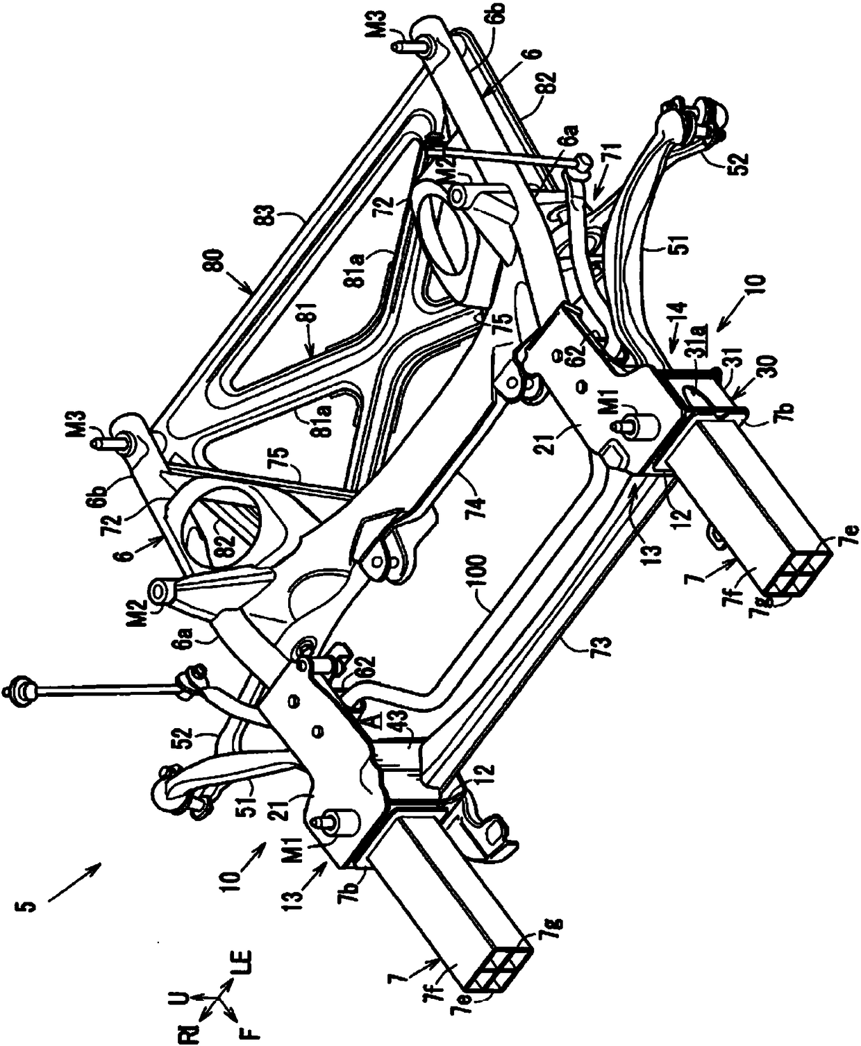
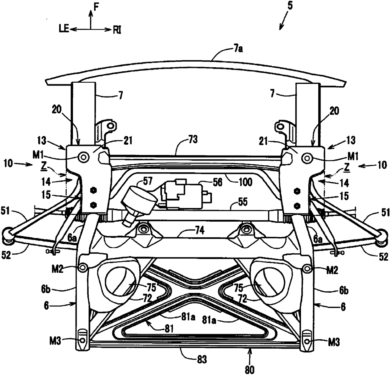
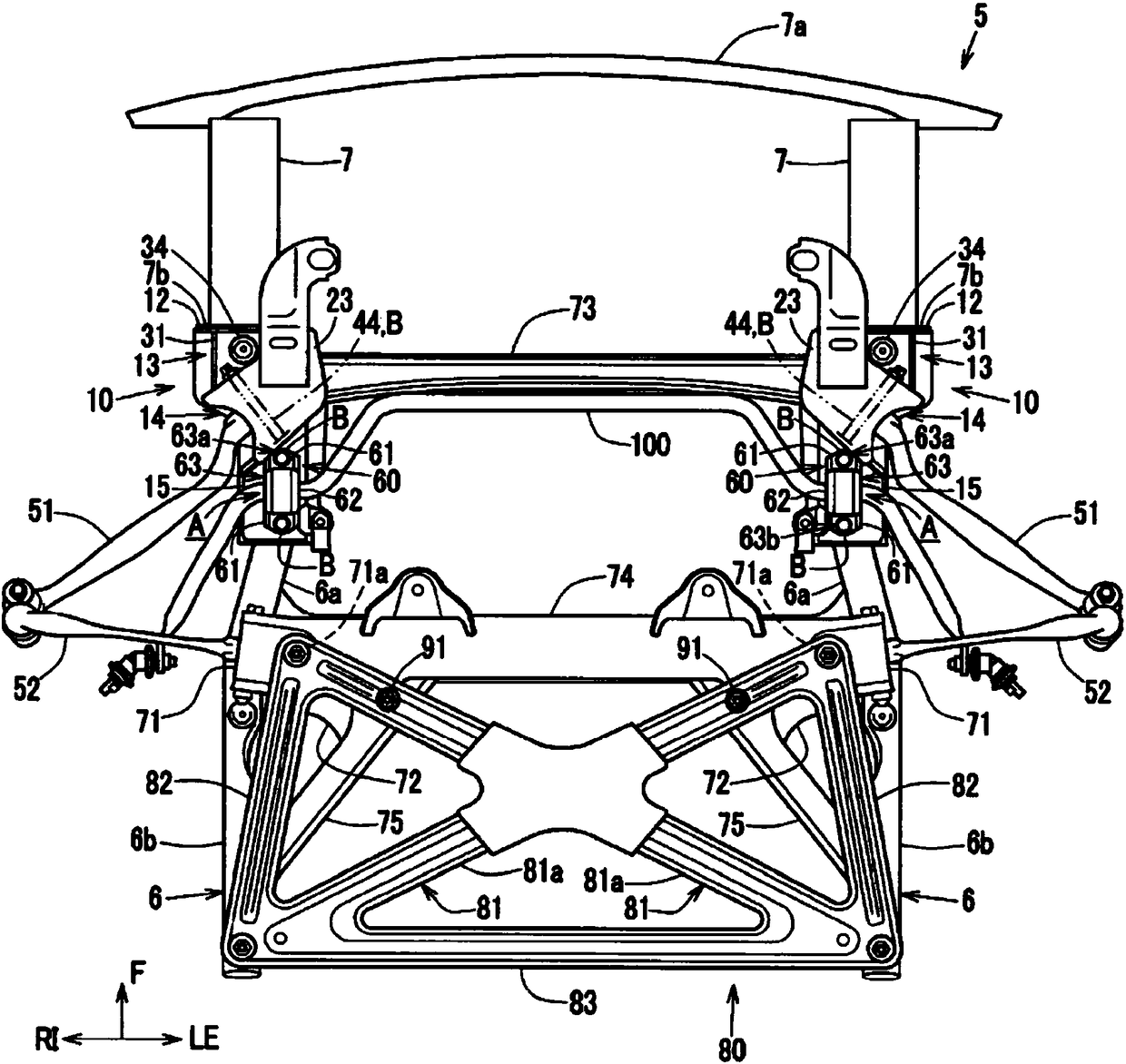
[0042] Figure 1 to Figure 7 The structure of the front subframe of the automobile of this embodiment is shown.

[0043] It should be noted that, in particular, figure 1 A perspective view showing the front subframe of the vehicle of this embodiment viewed from the front and obliquely above the left, Figure 7 An exploded perspective view showing a support frame seen from below and a front subframe with the support frame removed.

[0044] In the drawings of this embodiment, figure 2 In other figures, illustration of the steering rack 55, the power steering actuator (power steering motor) 56, and the power steering pinion 57 is omitted. Figure 4 The illustration of the pull rod 51 and the lower arm 52 is omitted, Figure 5 and Figure 6 The illustration of the sub-bumper reinforcement 7a is omitted, Figure 7 and later Figure 8 The above-mentioned sub-bumper reinfo...


PUM


Abstract

In order to increase tension rod support rigidity and sub crush can attachment rigidity, while forming a front sub-frame front section using a plate material, the present invention has a configurationwhereby: a sub crush can attachment section (12) and a tension rod support section (14) are provided in a front section of a front sub frame (5); a front-side vehicle body attachment section (13) isprovided between both; a suspension cross member (73) is provided in the front-side vehicle body attachment section (13) and the tension rod support section (14); the front-side vehicle body attachment section (13) comprises a sub crush can weight transfer member (30); and an upper surface section (21) of the front-side vehicle body attachment section (13) and a partition (33) in the sub crush canweight transfer member (30) extend in the vehicle front / rear direction, separated from each other.

Description

technical field [0001] The technology disclosed in this specification relates to a front subframe structure arranged under a front side member. Background technique [0002] Heretofore, a well-known front subframe has a sub-crash can mounting portion, a tie rod support portion, and a cross member extending in the vehicle width direction so as to face the tie rod support portion from the inside in the vehicle width direction. [0003] For example, the following proposals have been made for such a front subframe: as shown in the following patent document 1, the structure in which the tie rod support part 2 supports the crush box 1e; 2, there is also a front subframe structure such as a steering rack 7 arranged below the tie rod support portion 1a. [0004] In such a front subframe, in order to lower the load bearing point such as the frontal collision load, it is necessary to arrange the sub crush box as low as possible. [0005] On the other hand, although the steering rack...

Claims


Application Information

Patent Timeline
Patent Type & Authority Applications(China)
IPC IPC(8): B62D21/00
CPCB62D21/06B62D21/11B60R19/34B62D21/155
Inventor 小宫胜行田中正显
Owner MAZDA MOTOR CORP
Why Eureka
Try Eureka