Resin molded article and molding method thereof

a molding method and resin technology, applied in the direction of thin material processing, transportation and packaging, layered products, etc., can solve the problems of lowering affecting so as to increase the rigidity of the mount base, increase the rigidity, increase the effect of the rigidity

Active Publication Date: 2011-07-12
DAIKYONISHIKAWA CORP
View PDF10 Cites 2 Cited by
  • Summary
  • Abstract
  • Description
  • Claims
  • Application Information

AI Technical Summary

Benefits of technology

[0014]In the invention according to Claim 1, the hard skin layer with no pore is formed at the surface of the resin molded article while a large number of pores are formed inside the molded main body, thereby contemplating a lightweight resin molded article. Further, the mount base and a part of the molded main body between the inner mount base portion and the outer mount base portion are formed of a solid layer having no expanded layer, thereby increasing the rigidity of the mount base. Moreover, the inner mount base portion and the outer mount base portion are joined by the plural parts of the joint mount base portion, thereby increasing the rigidity of the inner and outer mount base portions in the radial direction of the through hole to increase the rigidity of the mount base as a whole further and to prevent the inner and outer mount base portions from being deformed or broken even upon receipt of large fastening force of a fastening jig.
[0015]In the invention according to Claim 2, the mount bases are protruded continuously from the respective face of the molded main body so that at least the respective inner mount base portions and the respective outer mount base portion are opposed to each other, so that the thickness in total of the solid layers forming the mount bases increases double, further increasing the rigidity of the mount bases.
[0016]In the invention according to claim 3, with the solid layer surrounding each mount base, the rigidity of the molded main body around the outer periphery of each mount base increases.
[0017]In the inventions according to claim 4, the hard skin layer with no pore is formed at the entire surface of the resin molded article while a large number of pores are formed inside the molded main body, thereby contemplating a lightweight resin molded article. Each mount base has at least a dual structure of the inner mount base portion and the outer mount base portion to increase a contact area with the mold, thereby being cooled faster. Further, the mount base portions, each of which has a small width, hardly receive influence of expansion of the fiber-reinforce thermoplastic resin accompanied by the capacity increase, so that the skin layer at each mount base is formed thicker than the skin layer at the molded main body. Moreover, the inner mount base portion and the outer mount base portion are joined to each other by the plural parts of the joint mount base portion, thereby increasing the rigidity of the inner and outer mount base portions in the radial direction of the through hole to increase the rigidity of each mount base as a whole and to prevent the inner and outer mount base portions from being deformed or broken even upon receipt of large fastening force of a fastening jig. Furthermore, protrusion of the mount bases from the respective faces of the molded main body increases double the thickness in total of the skin layers of the mount bases, thereby further increasing the rigidity of the mount bases. Particularly, in the invention according to Claim 5, the joint mount base portions provided at the respective faces of the molded main body do not overlap with each other as viewed in plan to increase parts that receive the fastening force of the fastening jig, thereby increasing the rigidity of the mount bases further.

Problems solved by technology

Therefore, when a resin molded article including a mount base continuously protruded from a molded main body is formed by the method according to Patent Document 1, the rigidity of the mount base is lowered, with a result that the mount base may be broken or deformed upon receipt of large fastening force of a fastening jig in mounting the resin molded article to a target member.

Method used


Image

  • Resin molded article and molding method thereof
  • Resin molded article and molding method thereof
  • Resin molded article and molding method thereof

Examples


embodiment 1

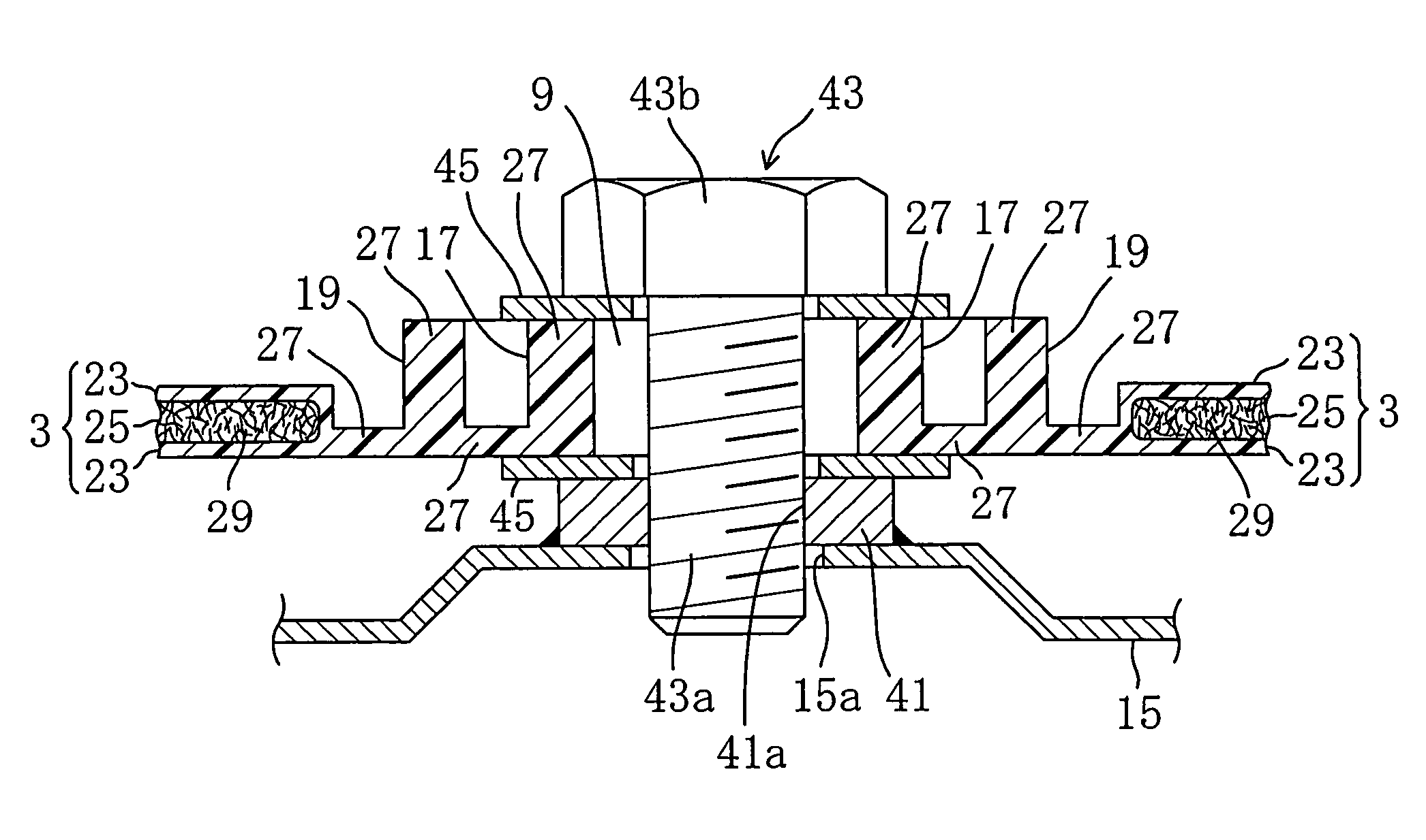
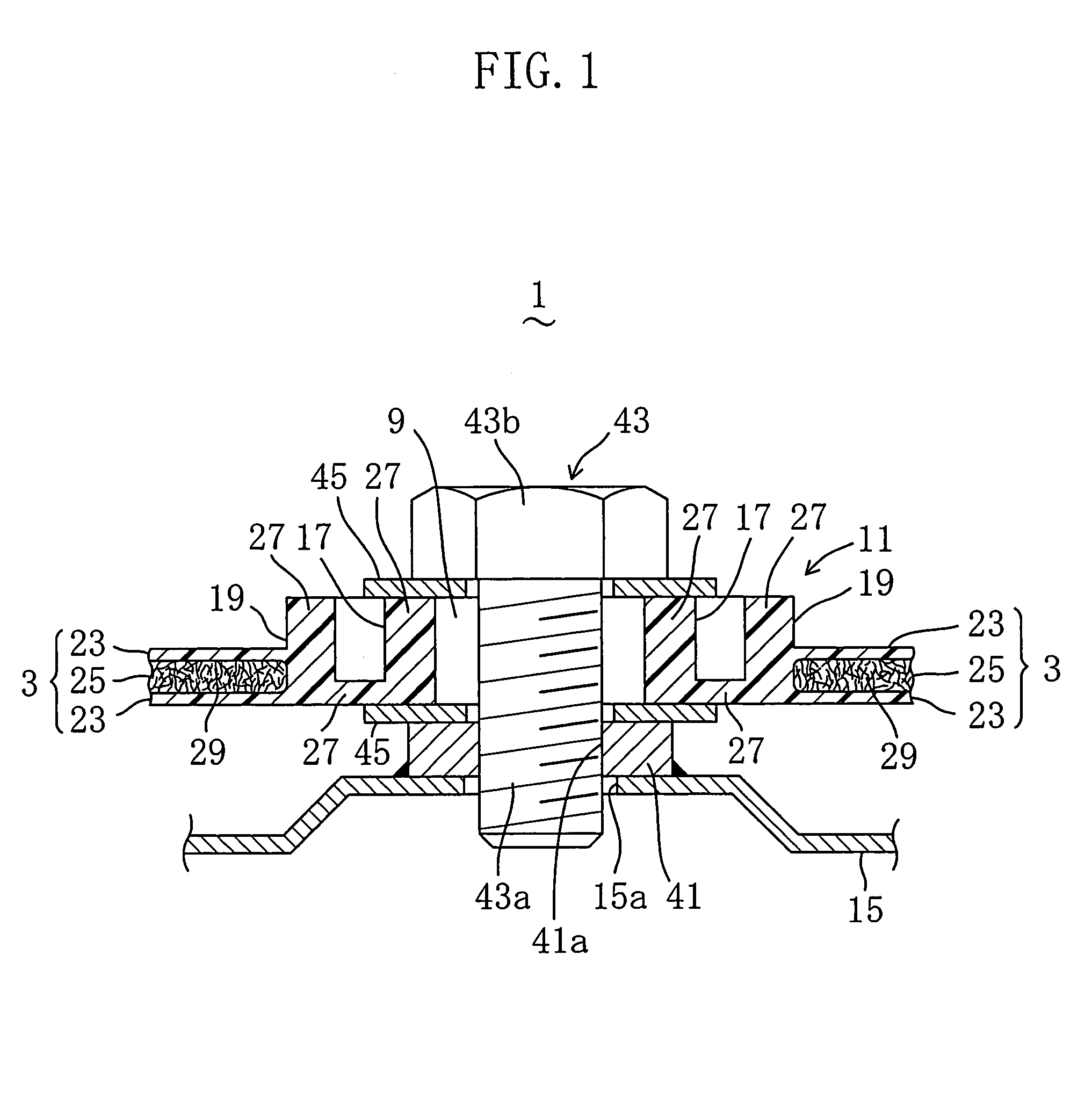
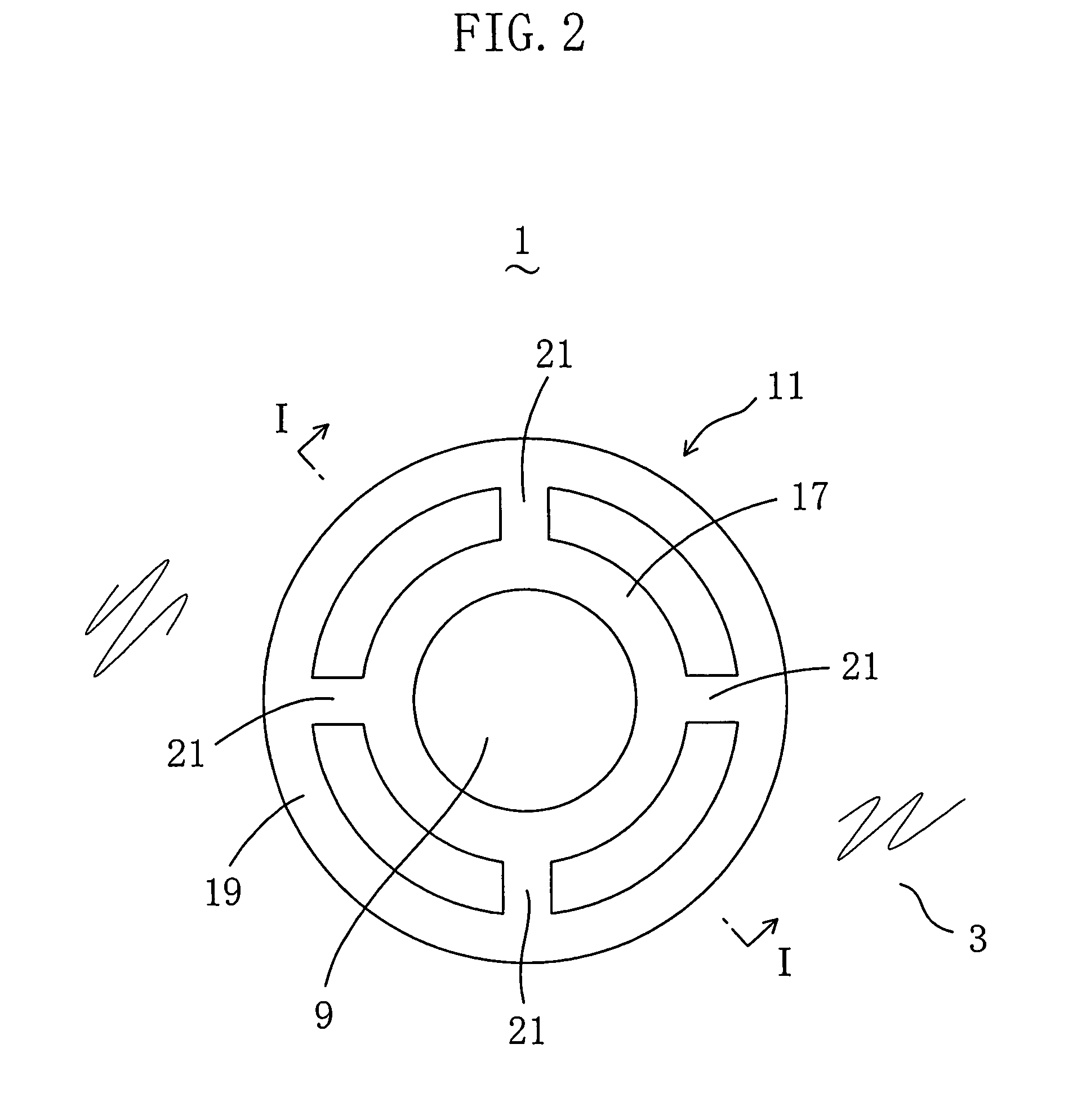
[0056]FIG. 3 is a perspective view of a resin-made door inner panel (door module) 1 forming a part of a side door for an automobile as a resin molded article according to Embodiment 1 of the present invention when viewed from the inside of a cabin. The door inner panel 1 includes a door inner panel main body (hereinafter referred to as panel main body) 3 as a molded main body, which has an inboard face from which four cylindrical mount bases 5 for mounting a window glass elevating rail (not shown) are protruded continuously. A speaker housing portion 7 in the form of a round flower pot is protruded continuously from the outboard face of the panel main body 3 at the left lower corner in FIG. 3. A plurality of through holes are formed at regular intervals in the peripheral part of the panel main body 3 along the entire periphery thereof, and an annular mount base 11 is protruded around the periphery of each through hole 9 continuously from the inboard face of the panel main body 3 so ...

embodiment 2

[0064]FIG. 6, which corresponds to FIG. 1, shows a door inner panel 1 as a resin molded article according to Embodiment 2, and FIG. 7 and FIG. 8 show molding steps corresponding to those of FIG. 4 and FIG. 5, respectively.

[0065]In Embodiment 2, mount bases 11 are protruded continuously from the respective faces of a panel main body 3 so that respective mount base portions 17, 19 are opposed to each other and are overlapped with each other when viewed in plan, wherein the mount bases 11 share a through hole 9.

[0066]Referring to a mold 37 used in Embodiment 2, concave portions 31b, 31c are formed in a first die 33 so as to be opposed to concave portions 35a, 35b of the pressure block 35, similarly to the pressure block 35, so as to correspond to the mount bases 11 opposed to each other and protruded from the respective faces of the panel main body 3.

[0067]The other part has the same structure as that in Embodiment 1, and therefore, detailed description thereof is omitted with the same...

embodiment 3

[0070]FIG. 9, which corresponds to FIG. 1, shows a door inner panel 1 as a resin molded article according to Embodiment 3.

[0071]In Embodiment 3, a solid layer 27 having a predetermined width and having no expanded layer 25 is formed at a part of a panel main body 3 around the outer periphery of each mount base 11 continuously from each mount base 11 so as to surround the outer periphery of the mount base 11. Correspondingly, a ring-shaped convex portion is formed outside a concave portion 35b in a pressure block 35 of a mold 37.

[0072]The other part has the same structure as that in Embodiment 1, and therefore, detailed description thereof is omitted with the same reference numerals assigned to the same constitutional elements. Description of a molding method thereof is also omitted.

[0073]Hence, the same effects as in Embodiment 1 can be obtained in Embodiment 3.

[0074]In addition, in Embodiment 3, with the solid layer 27 surrounding each mount base 11, the rigidity increases at a par...


PUM

PropertyMeasurementUnit
widthaaaaaaaaaa
thicknessaaaaaaaaaa
elastic restoring forceaaaaaaaaaa

Abstract

An annular mount base 11 continuously protruded from one face of a panel main body 3 and surrounding a through hole 9 has a dual structure of an inner mount base portion 17 and an outer mount base portion 19 which are joined to each other by four parts of a joint mount base portion 21. A skin layer 23 is formed at the surface of a door inner panel 1. An expanded layer 25 with a large number of pores is formed inside the panel main body 3. The mount base 11 and a part of the panel main body 3 between the inner mount base portion 17 and the outer mount base portion 19 are formed of a solid layer 27 having no expanded layer 25. Whereby, a lightweight resin molded article including a high-rigidity mount base is provided.

Description

TECHNICAL FIELD[0001]The present invention relates to an improvement on a resin molded article which has a molded main body from which a mount base is protruded continuously, at the surface of which a hard skin layer with no pore is formed, and inside which an expanded layer with a large number of pores is formed, and on a molding method thereof.BACKGROUND ART[0002]In Patent Document 1, a resin molded article at the entire surface of which a hard skin layer with no pore is formed and inside which an expanded layer with a large number of pores is formed is obtained in such a manner that: a fiber-containing thermoplastic resin is injected and filled in a cavity of a mold, which includes a fixed die having a molding face in which a concave portion is formed and a movable die including a sliding die, with the mold closed; and in the process of solidifying the fiber-containing thermoplastic resin in the cavity, the sliding die in the movable die is withdrawn in the direction in which the...

Claims


Application Information

Patent Timeline
Patent Type & Authority Patents(United States)
IPC IPC(8): B32B1/04B32B3/24
CPCB29C44/0415B29C44/586Y10T428/24496Y10T428/24479Y10T428/24273
Inventor MIYACHI, TOSHIKI
Owner DAIKYONISHIKAWA CORP
Why Eureka
Try Eureka