Fluid passage connecting device and refrigerating cycle apparatus having the same

A technology of fluid channels and connecting devices, which is applied in the field of refrigeration cycle equipment and can solve problems such as difficult sealing performance

Inactive Publication Date: 2012-11-28
DENSO CORP
View PDF11 Cites 6 Cited by
  • Summary
  • Abstract
  • Description
  • Claims
  • Application Information

AI Technical Summary

Problems solved by technology

However, the seal ring is arranged not only to limit the level difference but also to achieve the sealing performance to t

Method used


Image

  • Fluid passage connecting device and refrigerating cycle apparatus having the same
  • Fluid passage connecting device and refrigerating cycle apparatus having the same
  • Fluid passage connecting device and refrigerating cycle apparatus having the same

Examples


no. 1 example

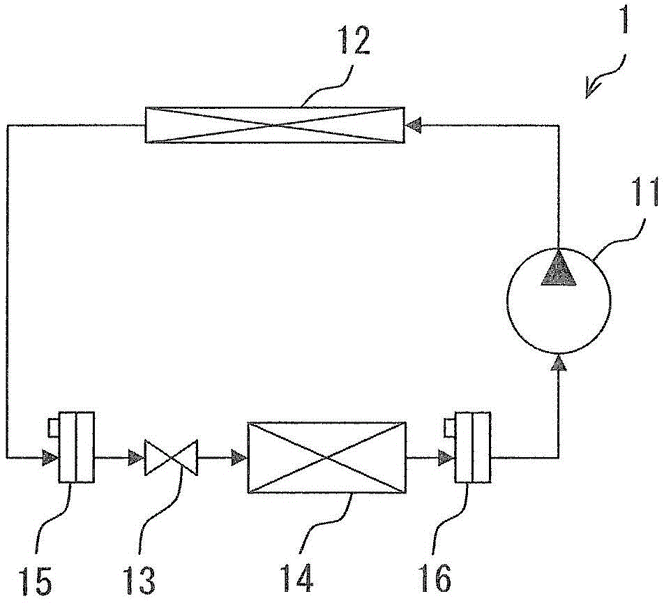
[0025] The fluid passage connecting device 16 according to the first embodiment is applied to the refrigeration cycle apparatus 1 mounted to a vehicle. The refrigeration cycle apparatus 1 corresponds to an air cooling device of an air conditioner that adjusts the temperature of air in a passenger compartment of a vehicle.

[0026] Such as figure 1 As shown, the refrigeration cycle device 1 has a compressor 11 , a condenser 12 , a pressure reducer 13 and an evaporator 14 in addition to a fluid channel connection 16 . A compressor 11 , a condenser 12 , a pressure reducer 13 , and an evaporator 14 are arranged in this order in a refrigerant circuit through which refrigerant flows.

[0027] The compressor 11 sucks and pressurizes low-pressure refrigerant, and discharges high-pressure refrigerant. The condenser 12 is a radiator that dissipates heat from high-pressure refrigerant to condense the refrigerant. The refrigerant is condensed by exchanging heat with the air outside the...

no. 2 example

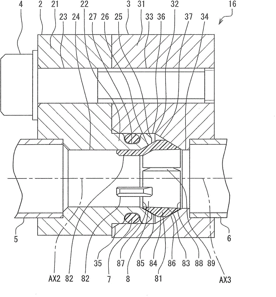
[0084] Figure 7 is a sectional view showing the fluid channel connection device 16 according to the second embodiment. Figure 8 is a perspective view showing the ring member 208 of the fluid channel connection device 16 of the second embodiment. In the first embodiment, the ring member 8 is securely held on the raised portion 22 by defining a plurality of protruding portions 82 .

[0085] In the second embodiment, the protruding portion 82 is eliminated in the ring member 208 of the second embodiment. The ring member 208 is held on the boss portion 22 by being inserted into the first tapered surface 85 to contact the first inner end surface 26 .

no. 3 example

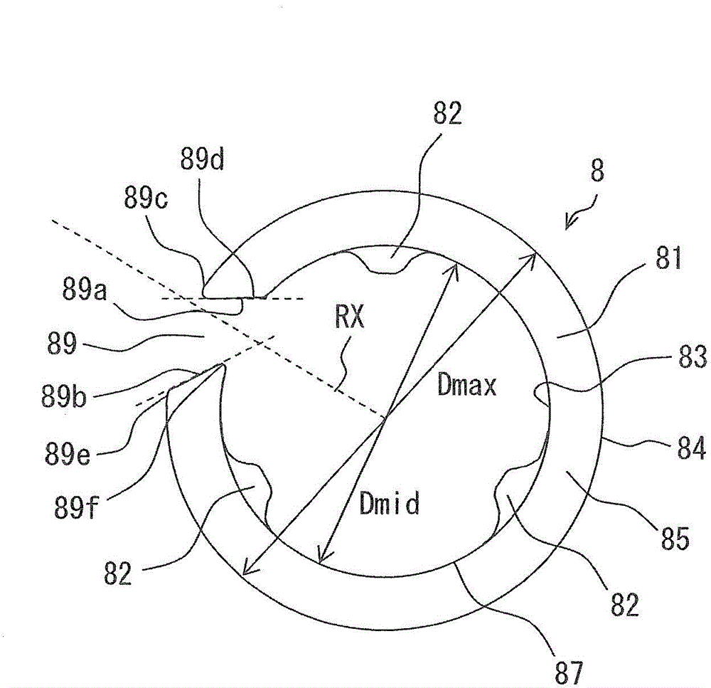
[0087] Figure 9 is a cross-sectional view showing the fluid channel connection device 16 according to the third embodiment. In the first embodiment, due to the discontinuity 89, the ring member 8 can be easily deformed.

[0088] In the third embodiment, the discontinuity 89 is removed in the annular member 308 . The ring member 308 can be deformed by the flexibility of the resin material. Therefore, even when the shapes of the first block 2 and the second block 3 have errors, the ring member 308 can be deformed to provide the inner surface 83 capable of limiting the variation of the passage sectional area between the passage hole 24 and the passage hole 34 .


PUM


Abstract

A first component and a second component are connected with each other in a manner that a first passage of the first component and a second passage of the second component communicate with each other through a communication part. A seal component is disposed between the first component and the second component to provide a sealing between the first passage and the second passage. A ring component is arranged to surround the communication part, and is located adjacent to the communication part rather than the seal component. The ring component restricts the communication part from having an excess increase in a cross-sectional area.

Description

technical field [0001] The present disclosure relates to a fluid channel connection device and refrigeration cycle equipment with the fluid channel connection device. Background technique [0002] JP-7-208661A, JP-7-217779A and JP-2008-57826A describe a fluid channel connection device having a male part and a female part. The male part has a convex part, and a sealing part such as an O-ring is arranged around the outer circumference of the convex part. A level difference is created on the inner surface of the fluid channel when the male part is joined with the female part to define the fluid channel. In addition, a gap is generated in the axial direction between the tip of the male part and the inner wall of the female part. Gaps cause fluid turbulence, and fluid turbulence causes noise. [0003] JP-3936697B2 (US 2004 / 0178631 , USP No. 6,969,094) describes a fluid channel connection device with a male part and a female part. The male part has a raised portion, and a seal...

Claims


Application Information

Patent Timeline
IPC IPC(8): F16L19/03
CPCF16L23/22F16L41/086F25B41/003F25B41/40
Inventor 渡边裕志东原昭仁松田俊和
Owner DENSO CORP
Why Eureka
Try Eureka